Piezoresistive Transducer Characterization and Subsea Pressure Sensing
Accurate subsea piezoresistive sensing demands third-order polynomial mapping across temperature and hydrostatic pressure to eliminate catastrophic seabed drift.

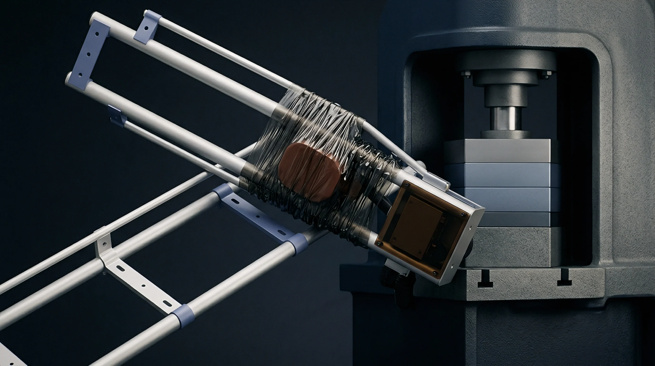
Wafer
Hydrostatic pressure at three thousand meters benthic depth registers 30.1 megapascals against the sensor face while seawater temperature hovers near 1.8 degrees Celsius. These conditions compress the microelectromechanical sensing structure, driving mechanical strain directly into the monocrystalline silicon element. The piezoresistive effect governs this conversion, changing bulk electrical resistivity when mechanical stress deforms the crystal lattice.
Piezoresistive silicon gauges achieve gauge factors exceeding one hundred, delivering signal sensitivity two orders of magnitude above conventional bonded metallic foil strains. Silicon exhibits severe temperature dependency. Uncompensated thermal sensitivity coefficients degrade raw accuracy if left uncorrected.
Transducer design begins by etching a thin bending diaphragm into a micromachined silicon die through anisotropic wet etching with potassium hydroxide or deep reactive-ion etching. The diaphragm measures twenty microns. Four distinct piezoresistors occupy the perimeter edges of this diaphragm where bending strain reaches peak concentration during fluid displacement.
Compressive stress along one coordinate axis pairs with tensile stress along the orthogonal axis. Wiring these four elements into a closed Wheatstone bridge circuit converts physical displacement into a proportional differential millivolt output signal.

Implanted Resistor Networks on Silicon Substrates
Boron dopants diffused into crystalline matrix planes form four balanced piezoresistors configured as a Wheatstone bridge. P-type doping profiles inside an n-type substrate define localized conduction channels with nominal sheet resistances typically bounded between five hundred and one thousand ohms per square. Bridge resistance measures five kilohms.
Maintaining identical thermal coefficients across all four bridge arms demands uniform dopant concentrations during ion implantation. Small variations in boron distribution induce initial offset imbalances across the bridge output terminals before external hydrostatic loading begins.
Dielectric isolation prevents parasitic junction leakage currents under elevated ambient thermal bands. Silicon-on-insulator fabrication sandwiches an insulating silicon dioxide layer between the active piezoresistive device layer and the base silicon handling substrate. This buried oxide boundary eliminates pn-junction reverse-bias leakage currents that degrade conventional diffused sensors operating past eighty degrees Celsius.
Subsea wells expose instrumentation packages to elevated reservoir temperatures up to one hundred fifty degrees Celsius alongside benthic chilling. Silicon-on-insulator technology confines electrical conduction pathways exclusively to the active resistor network across these thermal swings.

Orientation Mechanics along Crystallographic Axes
Current flow aligned with the 110 direction maximizes the longitudinal piezoresistive coefficient while minimizing transverse cross-axis sensitivity. Silicon exhibits cubic crystal symmetry, making piezoresistive coefficients anisotropic across different planes. Selecting the (100) silicon wafer orientation allows chemical etching along natural crystallographic stops, creating precise diaphragm thicknesses with flat sidewall geometries.
Four piezoresistors positioned along the orthogonal 110 directions on this face experience opposing fractional resistance changes under uniform hydrostatic deflection.
Output voltages swing with temperature. Applying a constant voltage excitation to the Wheatstone bridge produces a temperature-dependent span reduction because the fundamental piezoresistive coefficients decrease as thermal energy increases within the lattice. Supplying constant current excitation compensates for this drop by utilizing the positive temperature coefficient of bridge resistance.
Rising bridge resistance increases the excitation voltage across the bridge, counteracting sensitivity decline across standard ocean floor operating envelopes. Thicker isolation diaphragms protect against particulate damage while deadening dynamic pressure response across rapid thermal transients.


Seal
Subsea pressure transmitters isolate internal sensing chips from corrosive seawater through thin membranes machined from Hastelloy C-276 or Inconel 625. Direct contact with hyperbaric ocean water induces galvanic corrosion and swift chemical breakdown across exposed silicon microstructures. The metallic diaphragm sits on the wet process side of the sensor assembly, deflecting under hydrostatic head and transferring process force through an incompressible hydraulic fluid to the internal silicon chip.
Seawater corrodes exposed thin metals. Selecting corrosion-resistant alloys preserves structural integrity across twenty-year design lives.
Helium leak rates exceed limits. Electron-beam welding joints the outer perimeter of the isolation membrane to a rigid stainless steel or titanium header body, establishing a hermetic boundary. Any microscopic void within this welded seam permits hydraulic fluid leakage or seawater ingress, destroying measurement accuracy.
Glass-to-metal seals route electrical conductors out of the sealed internal cavity toward amplification electronics, containing internal fill fluid while insulating signal lines under extreme external hydrostatic pressure heads.
Trapped micro-voids inside transducer silicone oil cavities expand under warm surface handling and collapse under deep hydrostatic immersion.
Pressure port design must accommodate violent ocean currents and sediment accumulation. Flush-mount diaphragm profiles prevent particulate sedimentation from clogging narrow impulse lines on subsea production manifolds. Recessed cavities protect diaphragms from direct impact during subsea remotely operated vehicle installation maneuvers, yet recessed dead legs risk hydrate and wax deposition in high-viscosity oil production environments.

Fluid Fill Dynamics within Hermetic Cavities
Pure polydimethylsiloxane fluid transfers hydrostatic force from outer membranes to the inner chip cavity with minimal compressibility. Silicone oil formulations balance low thermal expansion coefficients with stable kinematic viscosity across the ocean spectrum. The total volume of hydraulic oil within the sensor header directly controls overall temperature sensitivity.
Silicone oil expands when heated. Thermal expansion of the trapped oil presses outward against both the flexible external isolation membrane and the internal silicon sensing diaphragm, producing an artificial pressure reading known as thermal volume shift.
Degassing procedures eliminate dissolved air and volatile fractions from the silicone oil prior to high-vacuum filling. Fluid processing subjects the fill fluid to vacuum stages below 0.01 millibar paired with thermal baking cycles. Introducing fluid containing trace air bubbles creates severe non-linear compliance; bubbles compress rapidly under initial hydrostatic loading, causing pronounced sensitivity deadbands near atmospheric pressure and sluggish step response times.
- Hydraulic cavity volume minimization reduces overall oil mass, suppressing measurement errors induced by fluid thermal expansion across fluctuating benthic water currents.
- Diaphragm stiffness matching ensures the external metal foil flexes freely without shunting mechanical strain away from the compliant silicon sensing element.
- Vacuum bakeout regimes remove absorbed moisture and organic volatiles from inner chamber walls before final fluid encapsulation and terminal pinching.
- Secondary glass headers prevent catastrophic fluid loss into sensitive digital processing electronics should the primary silicon chip fracture under severe pressure spikes.
When zero shift exceeds baseline bounds after hyperbaric cycling, supplier engineering representatives typically maintain that factory fill fluid degassed fully prior to electron-beam sealing and point instead toward client cabling mechanical strain.


Stress
Characterization routines map bridge voltage readouts against deadweight tester references across temperatures between minus two and forty degrees Celsius. Testing chambers apply stepped pressure sequences from barometric zero up to full ocean scale at 69 megapascals, dwelling at designated thermal plateaus to record stable resistance values. Zero shift reaches four millivolts.
Multi-point baseline verification establishes the boundary conditions for mathematical error compensation.
Raw silicon transducer outputs display non-linearities and coupled thermal cross-sensitivities that distort direct hydrostatic measurements. Uncorrected sensors exhibit full-scale errors exceeding five percent under standard subsea operational bands. Modern benthic instrumentation packages embed digital signal processors adjacent to the analog sensing cell to execute real-time mathematical corrections, transforming uncompensated analog bridge voltages into linearized engineering units.
A temperature deviation of two degrees Celsius shifts uncompensated piezoresistive bridge output by twelve millivolts at full scale ocean bottom pressure.
Thermal lag distorts transient curves. Internal transducer elements feature unequal thermal masses; the external metallic header, internal oil volume, and central silicon die warm and cool at different rates during rapid fluid discharge events. Piezoresistive temperature sensors diffused onto the same silicon die measure instantaneous die temperature rather than outer housing temperature, anchoring digital compensation algorithms to the actual physical state of the piezoresistive bridge.

Third Order Polynomial Calibration Schemes
Mathematical modeling correlates raw transducer output and onboard temperature sensor signals to generate calibrated pressure outputs. A two-dimensional third-order polynomial equation accounts for pressure non-linearity, temperature zero shift, temperature sensitivity drift, and cross-coupling terms:
P_cal = Sum over i from 0 to 3, Sum over j from 0 to 3 of (C_ij S^i T^j)
In this formulation, S represents normalized bridge output, T denotes normalized sensor temperature, and C_ij represents calibration coefficients extracted through least-squares surface fitting across factory calibration test points. Sixteen discrete matrix coefficients capture the intricate curvature of the piezoresistive surface response across combined pressure and thermal domains.
| Calibration Plateau | Applied Pressure (MPa) | Chamber Temp (°C) | Raw Output (mV/V) | Error (% Span) |
|---|---|---|---|---|
| Atmospheric Baseline | 0.10 | -2.0 | 0.02 | +0.04 |
| Shallow Intermediate | 15.00 | 4.0 | 5.88 | -0.08 |
| Mid-Depth Plateau | 35.00 | 15.0 | 13.72 | +0.12 |
| Full Ocean Rating | 69.00 | 4.0 | 27.15 | -0.05 |
| Thermal Shock Peak | 69.00 | 45.0 | 26.40 | +0.18 |
Calibration matrices require rigorous verification across independent check points located between original test nodes. Interpolation errors escalate if polynomial orders exceed physical fitting requirements, causing Runge phenomenon oscillations near calibration boundaries. Maintaining a balanced third-order fit suppresses mathematical oscillations while bounding residual non-linearity inside 0.05 percent of full-scale output.

Does Thermal Hysteresis Corrupt Seabed Piezoresistive Profiles?
Successive temperature cycling through ocean floor baselines shifts zero-point bridge balances away from factory baselines. Thermal hysteresis stems from mechanical stress relaxation across structural joints, including die-attach adhesives, glass headers, and welded metallic isolation diaphragms. Hysteresis introduces non-linear reading errors.
When components expand at divergent rates during temperature excursions, internal mechanical shear strains transfer into the silicon sensing diaphragm, shifting resting resistance values.
Die-attach materials dominate thermal hysteresis behavior. Rigid gold-silicon eutectic bonding creates high mechanical stability yet transfers thermal expansion mismatches from supporting headers directly into the silicon crystal. Compliant silicone or fluorosilicone adhesives absorb interface stresses, reducing instantaneous thermal stress but introducing time-dependent viscoelastic creep across sustained subsea deployments.
Hard solder glass bonding establishes an intermediate path, offering inorganic stability with thermal expansion coefficients matched closely to monocrystalline silicon.
- Die-attach coefficient matching minimizes interfacial shear strain across temperature transitions between deck assembly and benthic immersion.
- Annealing cycle stabilization relieves residual mechanical stresses inside isolation diaphragms prior to final electronic zero-point calibration runs.
- Bimodal thermal cycling verification measures residual zero offset after alternating excursions between hot surface storage and icy benthic baths.
- Full-scale pressure dwell checks ensure structural packaging elements return to original geometric datums without plastic deformation.
Miscalibrating third-order polynomial coefficients across deep-ocean thermal gradients produces phantom reservoir depletion calculations that shut down subsea production trees prematurely.

Fatigue
Continuous cyclic stress degrades physical packaging components across extended operational campaigns. While monocrystalline silicon exhibits zero mechanical hysteresis and near-infinite fatigue life below its brittle fracture limit, peripheral metallic diaphragms, weld seams, and electrical connections sustain cyclic fatigue damage. Repeated reservoir choke operations create high-frequency pressure pulsations superimposed onto massive hydrostatic base loads.
Mechanical fatigue manifests as micro-cracking across isolation foils, altering structural compliance over operational lifetimes.
Diaphragm rupture exposes delicate internal cavities to corrosive marine environments. Even before complete structural failure, metallic work hardening shifts isolation membrane stiffness, causing monotonic calibration drift. As the isolation diaphragm stiffens, higher proportions of applied hydrostatic force are absorbed by the metal membrane, reducing fluid pressure delivered to the internal silicon chip and generating false downward pressure measurement drift.
Compliance with ISO 13628-6 hyperbaric testing protocols penalizes sensor designs lacking secondary environmental glass seals behind primary isolation headers.
Long-term drift verification demands automated monitoring during extended environmental testing. Subsea installations cannot tolerate annual recalibration trips. Transducers must retain precision within 0.1 percent of span across five-to-ten-year deployment intervals without physical intervention.

What Drives Long Term Piezoresistive Sensor Drift?
Subsea instruments deployed at four thousand meters experience continuous hydrostatic loading punctuated by severe reservoir fluid pulsations. Long-term drift originates primarily from slow physical aging within the transducer package. Die-attach adhesive relaxation, slow outgassing of trapped trace elements into internal hydraulic oil, and atomic dopant migration within silicon resistor channels alter electrical balance over years of operation.
Bridge resistor drift alters transducer zero points independently of applied mechanical loads. Elevated temperatures accelerate dopant atom migration near silicon-oxide boundary interfaces, shifting absolute resistance values across individual bridge arms. Even a fractional resistance shift of 0.01 percent in a single resistor arm produces a substantial zero-reading offset error at full-scale signal processing resolution.
- Mechanical screening subjects bare transducers to one thousand hyperbaric pressure cycles, eliminating units displaying early weld seam fatigue or diaphragm yield.
- Thermal burn-in baking for one hundred sixty hours at maximum rated storage temperature stabilizes internal dielectric passivation layers and relieves die-attach shear strains.
- Baseline stability recording under static hydrostatic loading for thirty days establishes initial drift rates and identifies anomalous electronic components.
- Secondary hyperbaric screening tests verify that zero-point outputs remain within narrow tolerance bands following dynamic pressure cycling.

Hydrogen Permeation under Cathodic Protection Potentials
Impressed current cathodic defense systems running at minus one thousand millivolts generate monatomic hydrogen ions across titanium subsea housings. Hydrogen atoms penetrate isolation foils. Sacrificial aluminum or zinc anodes protect steel production structures from seawater corrosion by maintaining negative electrical potentials.
This electrochemical reaction produces monatomic hydrogen at metal surfaces exposed to seawater.
Cathodic protection accelerates hydrogen absorption. Atomic hydrogen diffuses through the thin metallic crystal lattice of Hastelloy and stainless steel isolation diaphragms over sustained subsea deployments. Upon reaching the internal cavity, hydrogen atoms recombine into molecular hydrogen gas within the silicone fill fluid.
Because molecular hydrogen cannot diffuse outward through the metal foil, gas accumulates inside the hermetic fluid chamber. Gas accumulation forms bubbles inside the hydraulic fluid, inducing massive zero-point drift, degrading frequency response, and eventually causing physical ballooning and rupture of the isolation diaphragm.
Whether silicon diaphragm piezoresistive micro-cracking initiates from cumulative mechanical strain cycles or from atomic hydrogen penetration through isolation membranes under cathodic protection remains an open question across deepwater operations.


Outlay
Deepwater subsea trees operating at three thousand meters demand continuous pressure monitoring over twenty-year field lifetimes. Instrument failure triggers astronomical operational interventions. Mobilizing an offshore light well intervention vessel or drilling rig to replace a failed pressure transmitter costs hundreds of thousands of dollars per day, with total intervention expenditures frequently surpassing twenty million dollars per campaign.
Subsea intervention costs escalate rapidly.
Procuring highly characterized, qualification-tested piezoresistive transducers represents a modest fraction of total subsea project capital expenditure. Standard industrial pressure transmitters cost under one thousand dollars, whereas hyperbarically qualified, hermetically sealed subsea transducers cost upwards of twenty-five thousand dollars per channel. This price delta reflects extensive environmental screening, individual multi-temperature polynomial mapping, material traceability certifications, and hyperbaric pressure test regimes designed to eliminate early infant mortality.
Subsea intervention vessel day rates turn minor calibration errors into multi-million dollar operational balance sheet write-downs.
Redundant architecture strategies balance unit acquisition costs against subsea intervention risk. Production control pods routinely deploy dual-redundant or triple-modular redundant transducer arrays to monitor critical barrier pressures. Redundancy allows control systems to identify and vote out drifting sensors through cross-channel consistency algorithms without shutting down production or launching emergency intervention operations.

Procurement Allocation for Pressure Transducer Spares
Operators budget capital for redundant instrumentation packages during initial engineering design phases. Factory calibration limits drift risk. Spending additional capital upfront on rigorous transducer qualification delivers massive payback by avoiding unplanned vessel mobilizations during field operations.
Transducer qualification programs must balance pre-commissioning testing costs against probabilistic intervention liabilities over the asset lifecycle.
Vessel day rates exceed expectations. Testing budgets allocated to hyperbaric characterization, long-term burn-in, and hydrogen permeation barrier testing reduce the statistical probability of premature seabed failures to manageable levels across multi-well subsea architectures.
| Hardware Tier | Testing Scope | Unit Cost (USD) | Deployment Failure Rate (%) | Intervention Risk (USD) |
|---|---|---|---|---|
| Commercial Off-The-Shelf | Standard Factory Baseline | 1,200 | 14.5 | 2,900,000 |
| Industrial Marine Grade | Basic Thermal Cycling | 6,500 | 6.2 | 1,240,000 |
| API 17F Qualified Subsea | Full Pressure and Thermal Mapping | 28,000 | 0.8 | 160,000 |
| Triple Redundant Seabed Pod | Complete Screening with Hydrogen Barrier | 95,000 | 0.1 | 20,000 |
| Assumes a standardized vessel mobilization and repair cost base of twenty million dollars multiplied by the ten-year probability of hardware failure. | ||||
Inserting API 17F environmental screening qualification terms directly into transducer purchase orders shifts replacement liability and retrieval vessel mobilization expenses back onto component vendors whenever subsea units drift beyond operational limits.