Subzero Polymer Cable Insulation Fatigue and Dielectric Testing
Subzero polymer cable insulation flex fatigue lowers dielectric breakdown voltage by introducing interfacial micro-voids that initiate partial discharge.
Frost
Polymer insulations subjected to temperatures between minus forty degrees Celsius and cryogenic levels undergo severe dynamic lattice stiffening as ambient thermal energy drops. Glass transition phenomena alter the compliance of cross-linked polyethylene, ethylene propylene rubber, and fluorinated ethylene propylene, shifting elastomeric formulations into rigid states. Standard room-temperature datasheets fail to predict performance when thermal expansion differentials create high localized stresses along the conductor sheath interface.
Molecular Stiffening Dynamics
Subzero operating envelopes alter the free volume within cross-linked polyethylene and fluorinated ethylene propylene matrix networks. At ambient conditions of twenty degrees Celsius, polymer backbones exhibit segmental mobility, dissipating mechanical loads through micro-Brownian movement. Dropping the thermal environment past minus thirty degrees Celsius freezes these rotational degrees of freedom, locking polymer chains into unyielding crystalline arrangements.
Cold shifts polymer chain elasticity.
Mechanical stress concentration shifts from broad dissipation zones into rigid inter-crystalline amorphous boundaries. The elastic modulus of cross-linked polyethylene increases from two hundred megapascals at room temperature to over fifteen hundred megapascals at minus fifty degrees Celsius. When cable assemblies undergo flexure in these conditions, localized stress concentration exceeds structural bond limits, generating micro-fissures across primary insulation walls.
| Insulation Material | Glass Transition Temp (°C) | Elastic Modulus at 20°C (MPa) | Elastic Modulus at -50°C (MPa) | Tensile Elongation Limit at -40°C (%) |
|---|---|---|---|---|
| Cross-linked Polyethylene (XLPE) | -120 to -100 | 220 | 1650 | 35 |
| Ethylene Propylene Rubber (EPR) | -60 to -50 | 15 | 480 | 85 |
| Fluorinated Ethylene Propylene (FEP) | -208 | 550 | 2100 | 15 |
| Silicone Rubber (SIR) | -120 to -110 | 8 | 95 | 140 |
Cryogenic Polymer Glass Transitions
Polymeric chains lose segmental mobility when operating temperatures fall near or below the glass transition threshold. Ethylene propylene rubber maintains flexibility deeper into negative thermal regimes than standard polyolefins due to its lower glass transition baseline. Fluorinated compounds maintain high dielectric breakdown fields but exhibit extreme rigidity under Arctic ambient conditions.
Thermal contraction during rapid temperature drops induces volumetric shrinkage up to three point five percent in unfilled polyolefins. Differential contraction between copper or aluminum conductors and surrounding polymer jackets generates radial tensile stress. When cold flexure adds mechanical bending loads to this thermal baseline, insulation jackets yield through brittle cracking rather than ductile deformation.
Cross-linked polyethylene retains eighty-two percent of its dielectric breakdown strength after five thousand flex cycles at minus forty degrees Celsius when strain rates stay under two percent per second.
Suppliers frequently assert that room-temperature tensile elongation metrics above four hundred percent inherently guarantee low-temperature flexural endurance.

Strain
Cyclic bending mechanics at cryogenic and Arctic temperatures induce multiaxial stress fields across the dielectric jacket. Cables installed on offshore wind platforms, Arctic drillships, and aerospace sub-systems experience combined tension, compression, and shear forces during dynamic flexing. Repeated flexural cycles lower the stress intensity threshold required for mechanical micro-fracture propagation.
Mechanical Fatigue Mechanisms under Flexure
Bending radius constraints dictate the shear distribution across outer conductor shields and underlying polymer jackets. Flexural loading pushes the outer radius of the insulation sheath into tensile extension while forcing the inner radius into compressive loading. Cold embrittlement alters shear thresholds.
Outer radius tensile elongation opens sub-surface voids within filled polymer compounds. Compressive forces along the inner radius induce buckling within shield tapes and metallic braid layers, driving sharp metallic edges into cold polymer insulation walls. The repetition of flexural strain cycles initiates shear cracking that grows toward the core conductor over time.
- Inter-spherulite micro-fissuring occurs when tensile strains exceed two percent at temperatures below the polymer glass transition point, initiating micro-void growth along crystalline boundaries.
- Interfacial delamination develops along the semi-conductive shield interface as differential expansion coefficient imbalances generate high shear stresses during subzero flexure cycles.
- Metallic shield strand intrusion emerges when cold-stiffened braid wire ends puncture embrittled outer insulation layers under combined bending and torsional tension.
- Compressive buckling voids form along the inner bend radius as stiffened polymer jackets buckle against inner conductor elements during low-temperature reeling operations.

Standardized Bending Cycle Protocols
Testing procedures under IEC 60811-504 and IEEE 1202 mandate low-temperature impact and mandrel flexure qualifications at targeted setpoints. The test sample wraps around a chilled steel mandrel at specified temperatures between minus twenty-five and minus sixty degrees Celsius. Mechanical stress accelerates dielectric aging.
Standard test cycles apply a fixed wrapping speed ranging from five to thirty turns per minute. Maintaining a constant strain rate during low-temperature evaluation prevents localized frictional heating from artificial relaxation of the polymer matrix. High strain rate testing reveals brittle cracking thresholds missed during static cold-bend evaluations.
Contractual acceptance under IEEE 1202 mandates zero partial discharge activity above five picocoulombs at two hundred percent rated voltage following cold mandrel wrapping.
Clause 8.4 of IEC 60811-504 mandates that insulation jackets showing visible micro-fissures under four-times magnification after subzero mandrel flexure trigger immediate lot rejection.
Rig
Cold-chamber instrumentation requires precise mechanical feedthroughs and high-voltage dielectric leads operating concurrently at minus sixty degrees Celsius. Environmental testing rigs must isolate the mechanical drive actuator from thermal condensation while maintaining stable electrical insulation along test leads. Inaccurate thermal profiling in subzero chambers creates artificial performance readings on cable insulation samples.
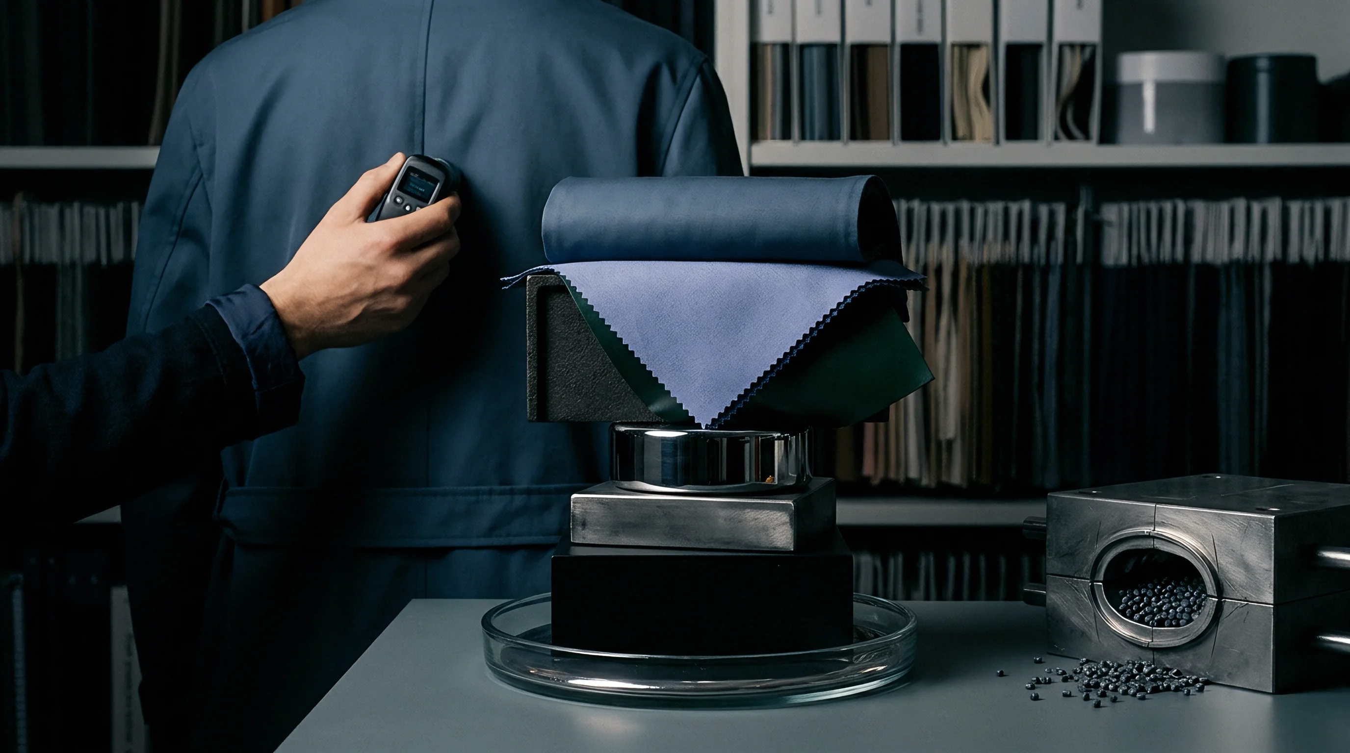
Cold-Chamber Setup Architecture
Environmental test enclosures maintain precise thermal regulation using liquid nitrogen injection valves calibrated alongside proportional-integral-derivative controllers. Mechanical flexure arms extend through double-walled insulated seals into the primary cold zone. Liquid nitrogen lowers chamber setpoints fast.
Bending actuators drive cable samples across variable radius mandrels inside the sealed thermal vault. High-voltage bushings routed through chamber walls utilize silicone insulation barriers treated with hydrophobic coatings to prevent ice accumulation. Frost deposition across high-voltage feedthroughs creates surface tracking paths, corrupting dielectric loss measurement instruments.
- Mount the pre-conditioned polymer cable specimen into the chamber mechanical clamps at ambient conditions, securing grounding shields to Earth leads.
- Evacuate ambient moisture using a dry nitrogen purge until chamber humidity drops below two percent relative humidity.
- Lower chamber temperature at a controlled rate of two degrees Celsius per minute until reaching the specified subzero target setpoint.
- Soak the mounted cable sample at the target temperature for four hours to ensure thermal stabilization across the full cable core radius.
- Initiate cyclic mechanical flexure using the pre-selected mandrel radius and bending velocity while logging actuator torque profile data.
- Apply continuous high-voltage screening potential across the conductor core and outer shield during mechanical flex cycles.
- Record partial discharge activity, capacitance changes, and dissipation factor values continuously throughout the cyclic test sequence.
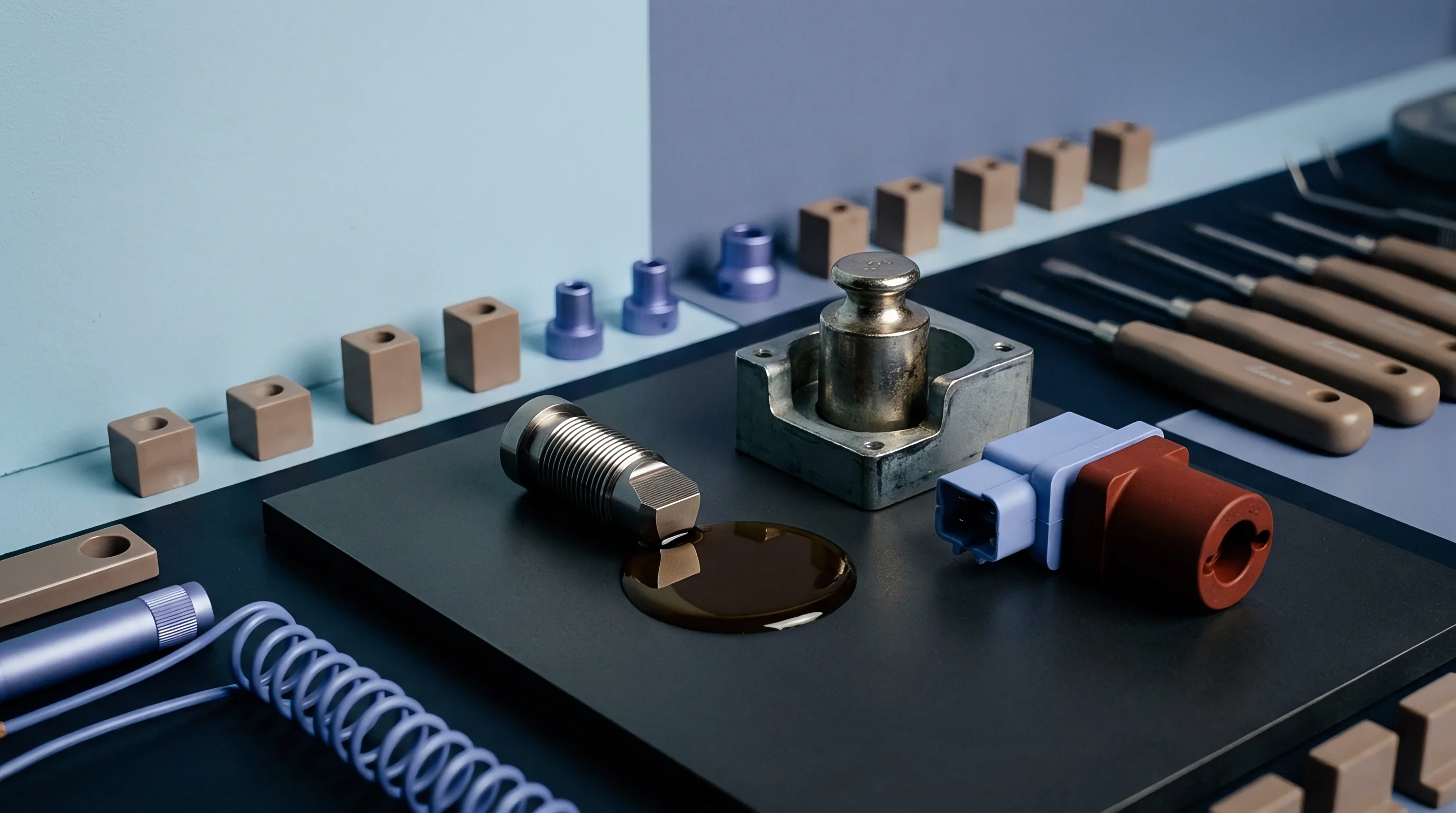
Dielectric Withstand and Partial Discharge Measurement
High-potential screening during subzero mechanical flexing detects localized micro-discharges before full insulation puncture occurs. Partial discharge detectors aligned with IEC 60270 standards measure charge displacement in picocoulombs during active bending. High voltage reveals micro-void formation.
Dielectric loss tangent measurements indicate structural degradation inside the polymer layer before visible surface cracking appears. An elevation in dissipation factor during cyclic subzero stress signals internal polymer chain scission and micro-cavity initiation. Continuous monitoring prevents sudden catastrophic dielectric breakdown during high-voltage proof testing.
Decreasing chamber temperature increases outer sheath stiffness, transferring mechanical fatigue loads directly onto inner primary insulation layers.
In subzero insulation bench evaluation, keeping actuator cycling speed low prevents internal friction from heating the polymer core above the target temperature.


Matrix
Electrical stress distribution across polymer layers changes radically when micro-fissures propagate under cyclic physical fatigue. Dielectric breakdown strength drops as mechanical damage forms local field enhancement points. Cold embrittlement alters shear thresholds.
What Dielectric Margin Prevents Subzero Shear Fatigue Failure?
Determining the residual breakdown strength of cross-linked insulation following ten thousand flex cycles requires assessing space charge accumulation. Mechanical stress concentrations alter the electrical insulation trap distribution within amorphous polymer regions. Trapped space charge distorts local electric fields, reducing macroscopic dielectric breakdown strength by up to forty percent.
Alternating current breakdown testing under ASTM D149 shows that un-fatigued XLPE withstands thirty-five kilovolts per millimeter at minus forty degrees Celsius. Subjecting the same material to five thousand flex cycles at minus forty degrees Celsius lowers the dielectric breakdown field to twenty-two kilovolts per millimeter. Shear stresses concentrate at inner bends.
| Flex Cycles Completed | Testing Setpoint (°C) | Partial Discharge Inception (kV) | AC Breakdown Field (kV/mm) | Dissipation Factor (tan δ × 10⁻⁴) |
|---|---|---|---|---|
| 0 (Baseline) | 20 | 12.5 | 38.0 | 2.1 |
| 1,000 | -20 | 11.8 | 35.2 | 2.8 |
| 5,000 | -40 | 8.4 | 26.5 | 5.4 |
| 10,000 | -40 | 5.2 | 21.0 | 8.9 |
| 10,000 | -60 | 3.1 | 15.8 | 14.2 |
Water Treeing and Electrical Treeing in Cold Envelopes
Subsurface voids formed through mechanical bending channel localized electric field lines, accelerating treeing phenomena despite low thermal activity. Water tree growth slows at sub-zero setpoints due to reduced moisture mobility, but mechanical micro-cracks replace chemical trees as primary failure drivers. Dynamic stress breaks polymer crosslinks.
Electrical treeing initiates at metallic inclusion tips or subzero fatigue cracks where electric field intensity exceeds local polymer dielectric strength. Once initiated, electrical trees propagate through brittle polymer structures rapidly under cyclic high-voltage stress. Micro-cracks destroy insulation integrity rapidly.
Uncertainty remains regarding whether space charge buildup in cross-linked polyethylene at minus sixty degrees Celsius permanently alters dielectric breakdown thresholds after ambient thermal recovery.

Defect
Structural anomalies induced by freezing mechanical deformation remain hidden during room-temperature pre-qualification procedures. Standard testing conducted at twenty degrees Celsius relaxes physical stresses within insulation jackets, masking subzero micro-fractures. Thermal recovery hides structural damage.
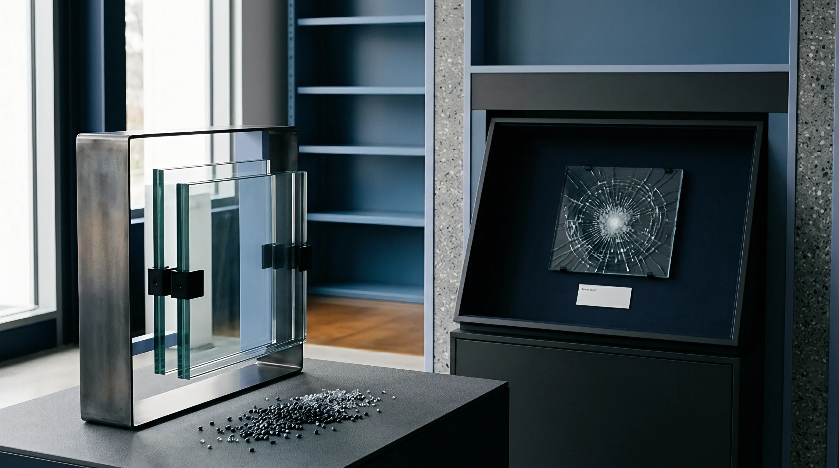
Micro-Cracking and Interfacial Delamination
Differential thermal contraction between copper conductors and outer polymer jackets creates shear stresses exceeding three hundred megapascals. When combined with dynamic flexing, this shear field strips the semi-conductive conductor shield away from the primary insulation layer. Polymer stiffness doubles at freezing setpoints.
Delamination creates an air gap along the inner conductor boundary. Air within these sub-millimeter gaps ionizes under operational electric fields, initiating continuous internal partial discharge. Partial discharge bombardment degrades surrounding polymer walls, leading to dielectric breakdown during routine voltage surges.
- Acoustic emission tracking captures ultrasonic elastic waves generated during micro-crack nucleation inside cold-chamber enclosures.
- X-ray micro-computed tomography resolves internal void geometries and interfacial delamination gaps down to two micron resolutions without warming the cable sample.
- High-resolution optical profilometry quantifies surface crack propagation paths along frozen polymer outer jackets following flexure cycles.
- Cryogenic broadband dielectric spectroscopy tracks shifts in high-frequency relaxation peaks to measure polymer chain scission rates under fatigue.
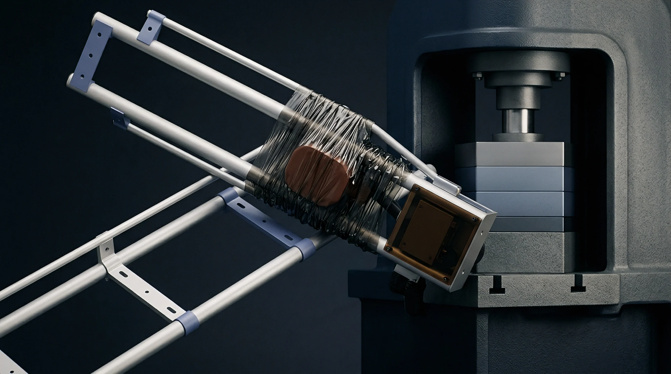
Field Qualification Failure Patterns
Wind turbine driveline cables operating in sub-Arctic locations experience jacket splitting along the inner bend radius within eighteen months of commissioning. Unverified jacket formulations rupture in service. Laboratory replication of these field failures confirms that room-temperature mechanical flex protocols failed to identify subzero strain fatigue vulnerabilities.
Flexural fatigue alters space charge density. Subzero fatigue shortens cable lifespan. Cables deployed without low-temperature dynamic flex qualification show an operational failure rate four times higher than pre-screened cable lots during winter weather events.
Interfacial micro-voids formed during low-temperature flexure initiate localized partial discharges that erode polymer chains before dielectric failure occurs.
Selecting unverified polyolefin jacketing for sub-zero trailing cables leads to unannounced insulation sheath rupture, conductor exposure, and emergency offshore operational downtime.


Ledger
Procurement specifications demanding minus fifty degree Celsius flex resistance add twenty-eight percent to raw insulation material expenses. Advanced fluoropolymers and modified cross-linked polyolefin compounds require specialized manufacturing controls and extended low-temperature validation testing. Upfront laboratory verification reduces field replacement risk exposure across project lifecycles.
Commercial Qualification Economics
Bench testing expenditures for forty-day cryogenic dielectric flex series range between fourteen thousand and twenty-two thousand dollars per cable formulation. Third-party laboratory audit reports establish compliance with client specifications before volume factory orders execute. Validation costs protect capital investment.
Assume a 500-meter umbilical subsea cable installation requiring 40-millimeter outer diameter cross-linked polyolefin insulation operating at minus forty-five degrees Celsius. A full qualification bench protocol involving twenty thousand flex cycles at five kilovolts alternating current carries a baseline testing price of eighteen thousand five hundred dollars. Comparing this against a project budget with a ninety-five thousand dollar insulation procurement lot shows testing costs accounting for nineteen point four percent of raw material acquisition.
If the qualification testing identifies a micro-cracking threshold at twelve thousand cycles, preventing field deployment of non-compliant insulation, the test expenditure averts an estimated six hundred forty thousand dollar subsea retrieval and repair operation.
| Project Risk Category | Standard Cable (No Subzero Flex Test) | Qualified Cable (Subzero Flex Verified) | Cost Impact Differential ($ USD) |
|---|---|---|---|
| Raw Cable Material Cost per km | $42,000 | $54,000 | +$12,000 |
| Laboratory Bench Qualification Fee | $0 | $18,500 | +$18,500 |
| Field Repair Risk per Circuit Failure | $640,000 | $0 (Mitigated) | -$640,000 |
| Net Financial Exposure (5 km Route) | $850,000 | $288,500 | -$561,500 |

Laboratory Testing Costs and Field Replacement Liabilities
Financial modeling shows that skipping low-temperature dynamic testing exposes offshore wind projects to offshore repair costs exceeding eight hundred thousand dollars per circuit. High-voltage offshore cable repairs require specialized vessel mobilization, jointing technicians, and long operational outages. Spending twenty thousand dollars on initial batch validation eliminates millions in unmitigated operational liabilities.
Commercial buyers balancing upfront lab validation budgets against long-term risk establish mandatory subzero dielectric flex verification clauses in every high-voltage cable RFQ.