Ultrasonic Noise Floor Calibration in High Pressure Valves
Calibrating ultrasonic valve noise floors requires isolating background fluid turbulence from true seat leakage signals using dynamic RMS threshold offsets.
Acoustics
High pressure drop across a closed or throttling valve valve generates fluid turbulent kinetic energy that converts into structural wave propagation across the valve body casting. When fluid passes through a narrow orifice or damaged seat interface under differential pressures exceeding 50 bar, acoustic emissions generate energy across a wide broad frequency spectrum from 20 kHz to over 500 kHz. Ultrasonic sensor arrays mounted on the exterior shell measure these stress waves through dry-coupled or wave-guide contact points.
The raw signal amplitude recorded at the transducer shell combines background hydrodynamic fluid noise, piping structural resonance, sensor thermal drift, and true seat leakage noise. Isolating the seat leak signal requires mapping the high pressure fluid background noise floor under non-leaking static and dynamic operational conditions.
| Frequency Band (kHz) | Dominant Acoustic Source | Attenuation Rate (dB/m) | Background Noise Floor Impact | Signal Detection Isolation Method |
|---|---|---|---|---|
| 20 to 40 | Pipe wall mechanical vibration and pump motor harmonics | 0.5 to 1.2 | High background amplitude; masks micro-leakage signatures | High-pass analog filtering at pre-amplifier stage |
| 40 to 100 | Turbulent jet mixing and valve trim flow shearing | 2.1 to 4.8 | Moderate amplitude; varies directly with flow velocity | Differential RMS offset baseline subtraction |
| 100 to 200 | High-velocity gas jet impact and micro-seat cavitation bubble collapse | 6.5 to 12.0 | Low ambient background; sensitive to internal seat turbulence | Windowed Fast Fourier Transform power spectral density analysis |
| 200 to 500 | Solid particle impact and severe localized liquid jetting | 15.0 to 35.0 | Near-zero ambient interference; high acoustic signal decay | High-gain localized sensor positioning within 50 mm of seat ring |
Acoustic wave attenuation through thick-walled cast steel valve bodies reduces high frequency energy rapidly over distance. A 100 kHz acoustic emission wave decays at approximately 8 dB per meter through carbon steel ASTM A216 WCC, whereas a 300 kHz wave decays at over 22 dB per meter in the same alloy matrix. Transducer placement relative to the internal valve seat geometry determines whether the recorded signal amplitude reflects localized seat erosion or background flow shearing through the downstream pipe bend.
Calibrating the acoustic floor involves isolating the structural energy generated by normal flow turbulence from the energy generated by pressurized fluid crossing a sealing interface gap down to 5 micrometers in width.
The background hydrodynamic noise floor rises exponentially with fluid velocity, doubling signal amplitude for every 12 percent increase in valve pressure differential.
Fluid density and thermodynamic phase changes across the valve orifice modify the base acoustic floor. Dry natural gas expanding across a choke valve generates fluid shear noise dominated by high velocity jet turbulence, producing broad acoustic energy around 60 kHz. Liquid hydrocarbon streams undergoing high pressure differential throttling generate micro-cavitation bubble collapse, producing localized transient acoustic spikes in the 120 kHz to 180 kHz range.
Baseline noise calibration routines must account for fluid temperature, upstream pressure variations, downstream backpressure stability, and fluid density fluctuations to prevent misinterpreting background hydrodynamic turbulent energy as seat pass-through leakage.
Equipment manufacturers routinely contend that high background acoustic readings during closed-valve testing originate from downstream piping turbulence rather than internal seat bypass.


Probe
Piezoelectric crystals inside ultrasonic transducers convert structural wall movement into millivolt electric signals. Transducer contact pressure, surface roughness, temperature stability, and couplant gel longevity fix the repeatability of the calibration reading. Physical installation defects alter transducer sensitivity curves, rendering background noise floor measurements inaccurate across operating temperature cycles.
Surface Preparation and Contact Pressure Tolerances
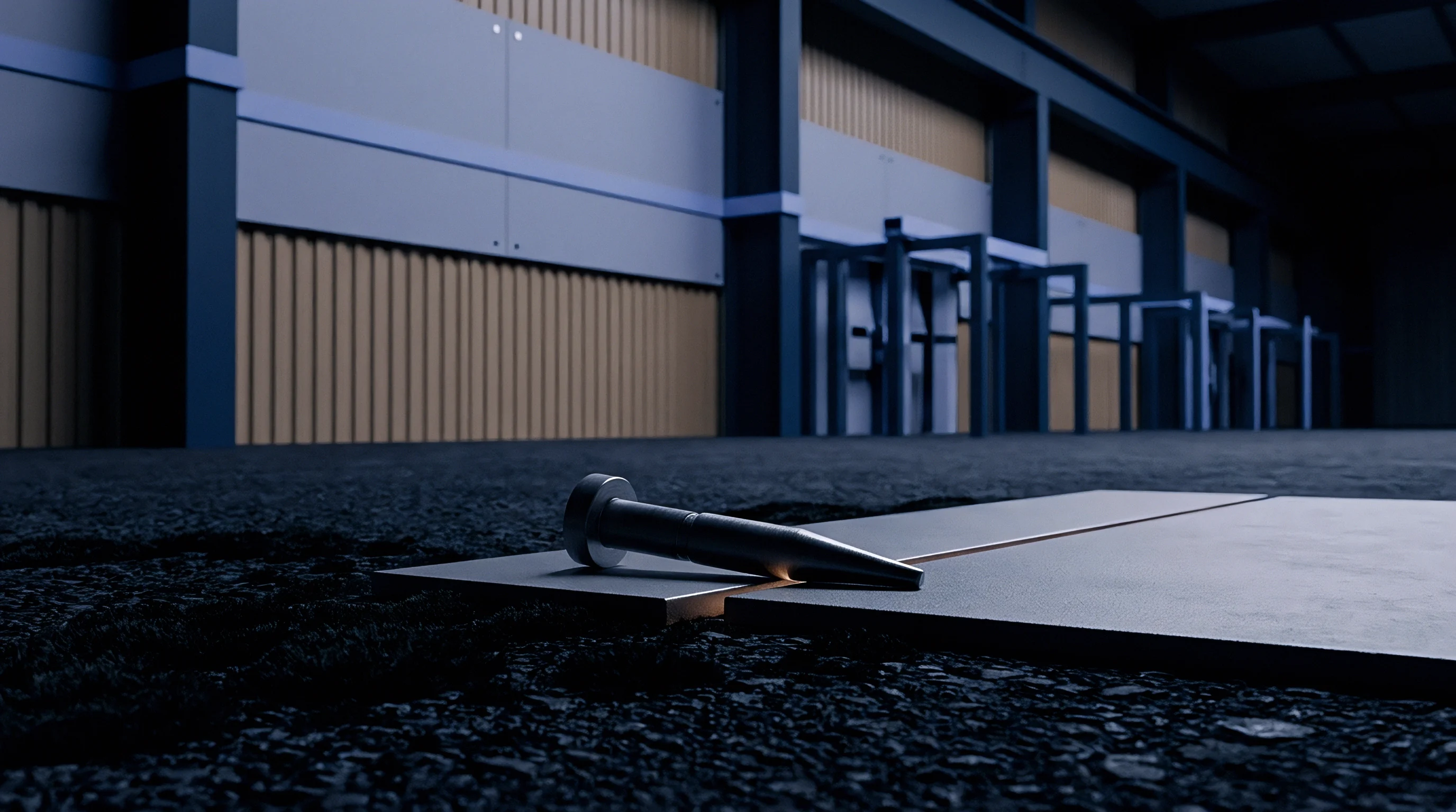
Mounting an ultrasonic sensor to a cast valve body requires preparing a flat surface flat to within 0.05 millimeters total indicator reading. Paint layers, surface oxidation, and casting scale act as acoustic attenuation barriers, attenuating signals by up to 14 dB at 100 kHz. Stainless steel magnetic hold-down clamps maintain a constant contact force between 15 and 20 Newtons, preventing sensor liftoff during operational pipe vibration.
Temperature fluctuations in high pressure steam lines thermal expansion shifts the sensor contact interface, introducing amplitude drift over continuous operating cycles.
ISO 18081 specifies continuous dry-coupling contact force verification for external wave-guide transducers operating above 150 degrees Celsius.

Transducer Signal Distortion and Mounting Anomalies
Calibration procedures fail when mounting defects introduce phase distortion or amplitude dampening before the pre-amplifier stage. Mechanical and acoustic installation failures alter signal integrity in identifiable ways.
- Couplant thermal degradation causes acoustic signal loss when standard silicone couplant dries or carbonizes at temperatures above 180 degrees Celsius, dropping signal transfer by over 20 dB within 48 hours.
- Magnetic clamp slippage occurs when line vibration forces the transducer hold-down bracket off center, changing sensor angle and creating signal attenuation variations up to 8 dB.
- Waveguide thermal expansion alters wave propagation speeds along high temperature standoff rods, creating artificial phase shifts in peak frequency response calculations.
- Sensor crystal depolarization occurs when operating temperatures exceed the Curie point of the piezoelectric element, causing permanent sensitivity loss without visible physical housing damage.
Sensor orientation on high pressure choke and globe valve bodies must align with the primary acoustic transmission path from the seat ring. Position the transducer on the valve body wall at an angle perpendicular to the seat plane, minimizing the wave transmission path through solid metal casting.
A transducer mounted with inconsistent contact pressure yields noise floor data that cannot be compared across operational shifts.

Threshold
Setting static signal thresholds above the ambient background level prevents false seat-leakage alarms while preserving sensitivity to small fluid losses. A threshold set too close to the background noise floor triggers false positive calls under routine flow surges. A threshold set excessively high misses early seat degradation, allowing seat washout to destroy trim components over extended operating windows.
Mathematical Noise Floor Offset Calculation
Consider a 6-inch Class 1500 choke valve operating under a differential pressure of 120 bar. Ambient plant noise, pump vibration, and structural pipe ringing produce a mean background acoustic emission signal amplitude of 28 dB relative to 1 microvolt at the transducer pre-amplifier output. The standard deviation of this background acoustic floor under steady flow conditions measures 2.4 dB across a 500-millisecond sampling window.
To establish a statistically valid noise threshold, calculate the upper limit using a confidence factor based on signal distribution variance. Selecting a standard deviation multiplier of 3.5 provides a false alarm probability below 0.03 percent under Gaussian noise distribution assumptions.
Threshold amplitude equals the mean noise floor plus the product of the confidence factor and standard deviation. Inserting the baseline numbers yields 28 dB plus 3.5 multiplied by 2.4 dB, resulting in a threshold limit of 36.4 dB. Acoustic signals exceeding 36.4 dB for longer than 200 consecutive milliseconds register as true seat bypass flow rather than background turbulence.
How Does Dynamic Hydrodynamic Noise Shift Calibration Limits?
Upstream flow variations shift the background acoustic signal dynamically during process operation. When process flow rates increase by 30 percent, fluid turbulence along the valve body casting elevates the mean background noise floor from 28 dB to 33 dB. Applying the static threshold of 36.4 dB under these high flow conditions reduces the effective signal margin to 3.4 dB, significantly increasing false positive leak alarms.
Dynamic threshold adjustment algorithms calculate the signal noise floor continuously using sliding temporal windows. The system recalculates baseline RMS values every 100 milliseconds, applying the standard deviation multiplier to the updated baseline. When fluid flow increases, the calibrated detection line steps upward automatically, maintaining constant detection sensitivity relative to the real-time fluid background noise floor.
Dynamic threshold adjustments require continuous differential pressure inputs to distinguish flow turbulence escalation from valve seat passing.
Engineers design windowed sampling routines to isolate intermittent fluid jetting from sustained seat leakage. Standard signal filtering protocols employ a 100-kilohertz high-pass filter paired with an integrated Root Mean Square converter, converting raw high-frequency stress waves into continuous decibel voltage equivalents for threshold comparison.
Contractual procurement specifications for high pressure gas valves mandate factory seat leakage acoustic baselines recorded at 1.1 times maximum rated differential pressure before delivery acceptance.

Baseline
Establishing baseline acoustic profiles requires mapping valve noise under controlled zero-leakage conditions prior to placing the assembly into active process service. Factory Acceptance Testing provides clean baseline curves under static water or nitrogen hydrostatic pressure. Field baseline profiles must capture background operational acoustic interference produced by adjacent equipment, control valve throttling downstream, and structural pipe resonances under full plant thermal equilibrium.

Differential Pressure Noise Calibration Parameters
Acoustic emissions scale directly with fluid pressure differential and seat gap geometry. Baseline calibration matrices document the signal rise generated strictly by differential pressure across a certified tight seat.
| Pressure Drop (bar) | Fluid Medium | Mean Noise Floor (dB ref 1µV) | Signal Variance (dB) | Calibrated Leak Threshold (dB) |
|---|---|---|---|---|
| 20 | Methane Gas | 22.1 | 1.2 | 26.3 |
| 50 | Methane Gas | 27.4 | 1.8 | 33.7 |
| 100 | Methane Gas | 34.8 | 2.5 | 43.55 |
| 180 | Methane Gas | 41.2 | 3.1 | 52.05 |
| 20 | Demineralized Water | 19.5 | 0.9 | 22.65 |
| 50 | Demineralized Water | 24.3 | 1.4 | 29.2 |
| 100 | Demineralized Water | 31.0 | 2.1 | 38.35 |
| 180 | Demineralized Water | 38.6 | 2.8 | 48.4 |
Signal calibration records must accompany high pressure valve dossiers to permit field verification over multi-year operating campaigns. Field inspectors compare active operational survey readings against factory zero-leak baselines to trace seat degradation rates over time.

Required Technical Documentation for Noise Floor Dossiers
Validation dossiers require explicit parameters recorded during baseline acquisition runs. Field technicians use these recorded constants to verify instrument calibration validity during site audits.
- Transducer serial number and sensitivity certification curve documenting resonant response frequencies within 1 dB accuracy across the 20 kHz to 300 kHz evaluation band.
- Couplant type and applied layer thickness specifications including temperature range ratings and mechanical attenuation coefficients.
- Upstream and downstream fluid temperature and static pressure logs recorded concurrently with acoustic signal acquisition windows.
- Piping structural vibration spectra measured between 10 Hz and 10 kHz to verify isolation from high-frequency acoustic emission channels.
- Pre-amplifier gain settings and filter bandwidth configurations matching field data collector hardware settings exactly.
Acoustic noise baseline profiles decay as sensor couplant ages under field exposure. Recalibrating background thresholds every six months maintains detection accuracy despite environmental degradation of the physical measurement interface.
How plant operators reconcile noise floor elevation caused by upstream trim erosion without taking the main valve offline remains a disputed point in process diagnostic protocol.

Validation
Commissioning an acoustic valve monitoring network requires executing sequential verification tests under live operational conditions. Field engineers prove system accuracy by introducing controlled acoustic noise sources or comparing detected amplitudes against measured physical seat drainage. Establishing verified noise floor benchmarks protects operators against premature valve replacement shutdowns caused by false acoustic alarm calls.

Sequential Field Calibration Procedure
Verification steps establish baseline sensitivity and confirm true signal response under operational line pressure.
- Mount the pre-calibrated ultrasonic transducer on the valve body acoustic measurement pad using a torque-wrench hold-down clamp set to 18 Newtons.
- Connect the sensor lead cable to the pre-amplifier, selecting a 40 dB gain setting and a 30 kHz to 200 kHz bandpass digital filter configuration.
- Isolate the valve downstream cavity, verifying zero process flow through physical bleed ports while maintaining full upstream line operating pressure.
- Acquire raw time-series acoustic emission data for 60 seconds to compute the static zero-leakage noise floor mean and standard deviation.
- Open downstream isolation valves to establish normal process flow across adjacent piping, recording dynamic acoustic floor elevation for 120 seconds.
- Calculate the operational threshold line by adding 3.5 standard deviations to the combined dynamic noise baseline amplitude.
- Simulate a seat bypass acoustic signal using a calibrated Nielsen-Hsu pencil lead break test on the valve bonnet flange to confirm wave propagation sensitivity.
- Lock the calculated threshold parameters into the continuous monitoring unit digital memory, tagging the valve dossier with timestamped calibration logs.
Inaccurate calibration parameters generate major commercial liabilities in severe service valve management. Setting an incorrect noise floor baseline masks real seat leakage, allowing high velocity gas jets to erode valve seat sealing faces in severe service choke applications. Unchecked seat erosion expands internal leak channels rapidly, converting minor internal bypass into catastrophic trim failure within weeks.
Replacing damaged valve trim requires un-bolting high pressure pipeline sections, forcing unscheduled unit shutdowns that incur costs exceeding $250,000 per day in lost production output.