Thermal Expansion Limits in Aerodynamic Thermoplastic Housing Design
Accommodate thermoplastic thermal expansion using kinematic sliding mounts and recessed lap joints to prevent out-of-plane buckling and boundary layer tripping.

Clearance
Aerodynamic thermoplastic enclosures encounter substantial surface temperature swings, running from negative forty degrees Celsius during high-altitude transit up to positive eighty-five degrees Celsius under solar soak. Unfilled polyetheretherketone expands at roughly forty-seven parts per million per Kelvin, while an underlying aerospace aluminum frame expands at twenty-three parts per million per Kelvin. Across a one-meter panel, that difference generates more than one millimeter of unconstrained relative growth.
If an exterior fairing binds against rigid bulkheads, it deflects outward into the freestream flow and trips the boundary layer from laminar into premature turbulence.
Flushness specifications on high-velocity surfaces tolerate step mismatches no larger than zero point five millimeters before parasite drag climbs sharply. An unplanned panel protrusion steepens local pressure gradients, pulling fasteners in tension and shedding vortices along the downstream trailing edge. Designing expansion channels into perimeter joints absorbs these dimensional shifts without driving up drag counts.
A one-meter polyetherimide fairing expands zero point eight four millimeters across a seventy-Kelvin operating rise against a carbon composite airframe.
Maintaining boundary layer attachment requires calculating perimeter gap widths at both thermal extremes. Cold soak contracts thermoplastic skins, opening gaps beyond acoustic tolerances and provoking cavity resonance. Peak thermal exposure closes those seams completely, generating compressive membrane stresses that lead directly to oil-canning.

Step Height and Gap Budgeting
Flushness calculations split permissible tolerances among baseline manufacturing variation, mounting compliance, and thermal displacement. Designers maintain positive margins by placing sliding datums along the primary axis of vehicle motion.
- Fixed Locating Pins anchor the forward leading edge flush with metallic hardpoints to secure the stagnation zone.
- Slotted Guide Bushings allow longitudinal growth along the airframe axis while resisting transverse flutter under high dynamic pressure.
- Elastomeric Edge Seals damp acoustic vibrations across temperature extremes without exerting compressive resistance against the expanding thermoplastic perimeter.
- Stepped Lap Joints mask thermal expansion gaps behind recessed lips, shielding internal avionics from direct moisture ingress.
Miscalculating joint allowances causes panels to buckle under peak heat, peeling surface coatings and permanently compromising aerodynamic efficiency across the craft.

Distortion
Uneven thermal fields across aerodynamic enclosures generate out-of-plane warping that compromises outer mold line profiles. Solar radiation bakes upper fairing surfaces while high-velocity air chills the underside, setting up a steep through-thickness gradient. The resulting internal bending moments pull thin-walled thermoplastic shells away from their calibrated contour.
Deflection changes local surface curvature. That shift relocates the suction peak on lift-generating cowlings, triggering separation bubbles that destabilize steady airflow. Measurable drag increases regularly register on precision balance scales long before any visible distress appears on the shell.
Uneven heating across shell thicknesses induces out-of-plane bowing that shifts aerodynamic suction peaks.
Thickening panel walls adds enough flexural rigidity to curb thermal bowing, but it brings severe mass penalties and drags out injection molding cycles. Thin-wall construction supported by integrated internal ribs distributes thermal stress across the structural envelope without surplus weight.

What Governs Transverse Panel Buckling?
Thin thermoplastic plates constrained between structural stringers buckle once compressive thermal stress exceeds the Euler critical load limit. In-plane expansion forces then relieve themselves by snapping into out-of-plane waves across unsupported spans.
| Polymer Compound | Tensile Modulus (GPa) | Flow CTE (ppm/K) | Cross-Flow CTE (ppm/K) | Heat Deflection Temp (0.45 MPa, C) |
|---|---|---|---|---|
| Unfilled PEEK | 3.8 | 47 | 47 | 250 |
| 30% Carbon Fiber PEEK | 13.0 | 11 | 32 | 315 |
| 30% Glass Fiber PPS | 10.5 | 18 | 42 | 265 |
| Unfilled PEI | 3.2 | 56 | 56 | 210 |
| Polycarbonate Copolymer | 2.4 | 65 | 65 | 145 |
Engineers evaluate post-buckling behavior by modeling the panel as an orthotropic plate under edge compression. The critical temperature delta depends directly on the ratio of shell thickness to unsupported span width. Introducing slight curvature raises buckling resistance without adding parasitic weight.
Structural analysts continue to investigate whether non-uniform pressure fields accelerate localized creep relaxation along the apex of thermally deformed fairings over multi-year deployment lifecycles.
Substrate
Reinforcing thermoplastic matrices with short or continuous fibers suppresses linear expansion along preferred flow paths. Melt dynamics align fibers parallel to fill directions, reducing the coefficient of thermal expansion along the injection axis while leaving the transverse axis dominated by raw polymer behavior. This anisotropic growth distorts circular mounting bosses into ellipses as operating temperatures rise.
High structural integrity demands close matching between reinforced housing shells and underlying frames. Carbon-fiber reinforced polyetheretherketone achieves thermal expansion parity with titanium substructures along its primary fiber orientation. Transverse expansion rates remain three times higher, generating severe inter-laminar shear loads at rigid fastening locations.
Reinforced polymers exhibit anisotropic expansion profiles that warp circular mounting holes into asymmetrical ellipses during thermal cycling.
Catalog specifications frequently treat thirty percent glass-filled compounds as dimensionally isotropic, but weld lines and gate locations dictate local expansion rates that deviate sharply from supplier ratings during production validation.
How Does Fiber Alignment Shift Linear Expansion?
Gating placement governs the directional fiber field throughout an aerodynamic component. Feeding from a single edge aligns reinforcement longitudinally down the fairing length, stabilizing the primary aerodynamic contour against freestream thermal growth.
| Housing Material | Substructure Material | Differential CTE (ppm/K) | Peak Joint Shear Stress (MPa) | Interface Compliance Strategy |
|---|---|---|---|---|
| Carbon PEEK (Longitudinal) | CFRP Skeleton | 9 | 12.4 | Standard Clearance Hole |
| Carbon PEEK (Transverse) | CFRP Skeleton | 30 | 41.2 | Radial Slotted Bushing |
| Unfilled PEI | Aluminum 6061-T6 | 33 | 45.8 | Spring-Loaded Shoulder Screw |
| Glass Fiber PPS | Titanium Grade 5 | 10 | 14.1 | Countersunk Floating Washer |
| Values calculated assuming a joint clamp length of 5.0 mm and clamping torque calibrated to 4.5 Nm. | ||||
Fiber orientation turns chaotic around parting lines and internal wall intersections, creating localized stress risers. Placing gates near aerodynamic stagnation lines maintains consistent fiber flow across critical boundary layer surfaces.
Polymer compounders continually balance fiber fractions against surface roughness requirements. Higher fiber loadings depress thermal expansion rates while degrading the mirror-grade finishes demanded by laminar flow airfoils.

Fastener
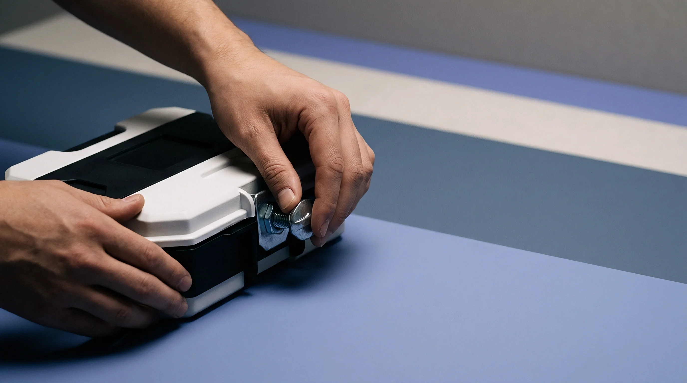
Mechanical joints linking thermoplastic housings to rigid subframes must accommodate continuous thermal movement without losing bolt preload. Clamp retention deteriorates when viscoelastic plastics experience compressive stress relaxation beneath standard metallic bolt heads. Elevated temperatures accelerate polymer creep, prompting joint loosening and subsequent panel flutter under aerodynamic buffeting.
Specialized shoulder bolts and precision compression limiters isolate thermoplastic flanges from direct clamp pressure. Metallic inserts route clamping loads straight into the underlying frame, leaving the plastic skin free to float within designated clearance channels.
Compression limiters absorb fastener clamp loads to preserve joint torque across extreme temperature cycles.
Countersunk fasteners introduce severe local hoop stresses when plastic expands radially against rigid conical bolt seats. Flat pan-head fasteners combined with oversized floating washers distribute retention forces uniformly without creating wedging mechanics.

Joint Kinematics and Retention Architecture
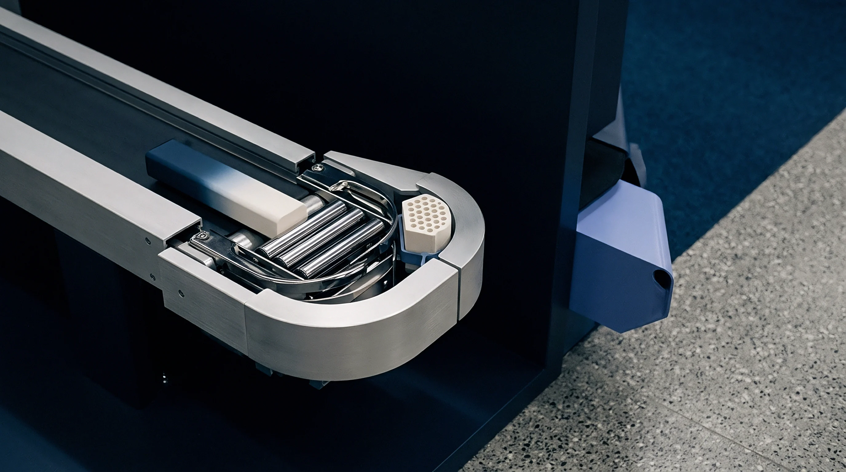
Design teams implement mechanical slip joints to decouple thermal displacement from structural stiffness. Specific hardware arrangements prevent premature joint fatigue:
- Passivated Stainless Steel Shoulder Screws establish repeatable mechanical standoff heights above the plastic flange surface.
- Fluoropolymer Coated Isolation Washers minimize sliding friction between bolt heads and painted thermoplastic fairing faces.
- Beryllium Copper Belleville Springs maintain continuous axial tension during thermal contraction phases at sub-zero temperatures.
- Symmetrical Radial Expansion Slots guide dimensional growth outward from the aerodynamic stagnation center point without binding.
Standard aerospace procurement documentation mandates that non-metallic exterior fairing attachments retain positive clamping retention across all qualification regimes under RTCA DO-160 Section 5 thermal cycling without exhibiting joint slip exceedances.
Envelope
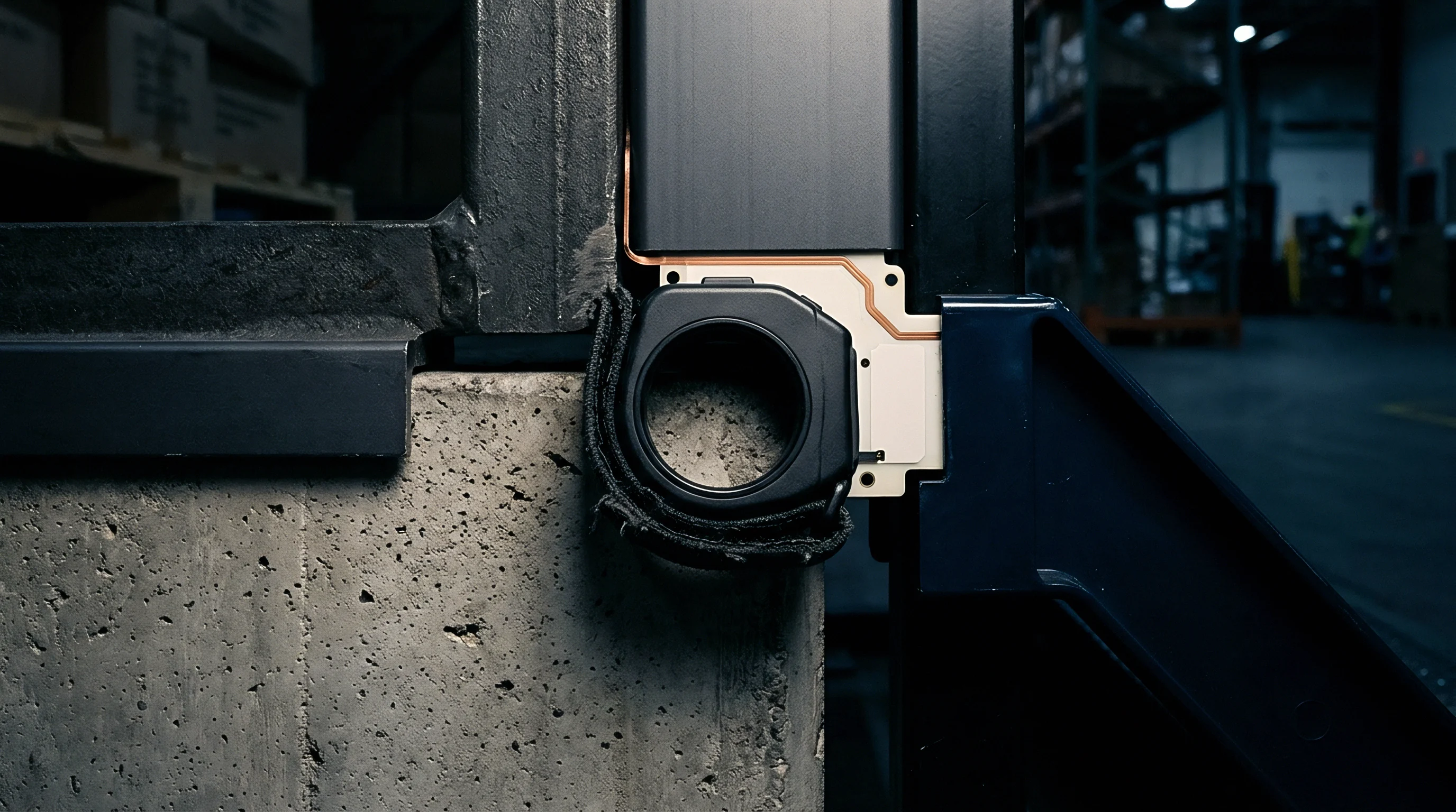
Validating aerodynamic enclosures demands thorough environmental testing inside climatic wind tunnels under combined thermal and aerodynamic loads. Test engineers track surface profile changes in real time using stereo photogrammetry and optical displacement gauges. Infrared thermography maps surface heat distribution during full-scale power runs.
Testing evaluates drag increments across cold soak, nominal cruise, and peak aerodynamic heating states. Shells that measure flush on a static inspection bench often distort under combined aerodynamic suction and elevated skin temperatures. Dynamic pressure scales with airspeed, turning minor thermal deflections into substantial drag penalties.
Verification protocols track dimensional recovery following thermal cycling. Plastics exhibiting residual strain or incomplete elastic recovery accumulate permanent mold line distortions over repeated thermal cycles. Permanent deformations degrade baseline aerodynamic performance and require complete panel replacement.
Boundary layer instrumentation measures skin friction drag across panel joints during thermal transients. Pressure taps arrayed along the housing surface record localized gradient shifts caused by thermal steps. Engineers compare physical drag count telemetry against computational fluid dynamics models to confirm flight readiness.
Production releases proceed only when full-scale articles prove dimensional stability across all environmental envelopes. Tooling adjustments compensate for measured thermal growth vectors before mold steel hardening. Finished thermoplastic aerodynamic housings deliver calibrated laminar flow performance across their operational lifespan.