Designing Kinematic Fastener Joints for Temperature Stressed Exterior Composite Fairings
Kinematic fairing joints isolate thermal strain by pairing fixed locating pins with precision-slotted floating inserts, preventing dynamic lockup and matrix failure.
Constraint
Exterior aerodynamic fairings mounted to aircraft structures or spacecraft hulls experience extreme temperature shifts across operational envelopes. Ambient conditions ranging from -55 °C at high altitude to +80 °C during ambient ground soak create significant thermal expansion differentials between carbon fiber reinforced polymer laminates and metallic substructures. Quasi-isotropic carbon epoxy panels exhibit coefficients of thermal expansion near 1.2 × 10⁻⁶ /K, whereas aluminum 7075-T6 airframe ribs expand at 23.0 × 10⁻⁶ /K. Titanium Ti-6Al-4V substructures present a moderate expansion rate of 8.6 × 10⁻⁶ /K. When rigid multi-bolt patterns join these materials without slip accommodation, thermal differential growth forces structural bending, fastener shearing, and matrix micro-cracking in the composite panel.
Kinematic mounting principles isolate thermal strain from structural load pathways. Isolating these deformations requires restricting exactly six spatial degrees of freedom without creating redundant mechanical boundary conditions. A classic 3-2-1 kinematic joint pattern fixes one primary reference hole, aligns a secondary hole along an elongated radial axis, and lets all remaining mounting points float tangential to thermal vectors.
The fixed location anchors the fairing relative to the primary airframe datum, taking all lateral shear and axial thrust forces. The secondary slotted locating hole prevents panel rotation while permitting radial sliding as the airframe frame swells or shrinks. Surrounding attachment points utilize floating sleeve inserts or oversize clearance holes with spring-energized washers, accommodating multi-directional thermal growth while maintaining out-of-plane clamping forces.
| Material Designation | Coefficient of Thermal Expansion (10-6 /K) | In-Plane Modulus (GPa) | Ultimate Pin Bearing Strength (MPa) | Galvanic Potential Relative to Carbon (V) |
|---|---|---|---|---|
| Carbon Epoxy Quasi-Isotropic Laminate | 1.2 | 54.0 | 480 | 0.00 |
| Carbon Epoxy Unidirectional Lay-up (0°) | -0.5 | 135.0 | 620 | 0.00 |
| Aluminum 7075-T6 Substructure | 23.0 | 71.7 | 380 | -0.80 |
| Titanium Ti-6Al-4V Grade 5 | 8.6 | 113.8 | 890 | -0.25 |
| Stainless Steel 316L Substructure | 16.0 | 193.0 | 620 | -0.35 |
| Inconel 718 Fastener Alloy | 13.0 | 205.0 | 1100 | -0.10 |
Calculating the expansion stroke across the panel span determines the minimum required slot length. For a composite fairing panel measuring 1200 mm between extreme fastener holes attached to an aluminum structure subjected to a temperature differential of 100 K, the absolute expansion delta reaches 2.616 mm. Standard fastener clearance holes specified under aerospace tolerances provide less than 0.25 mm of lateral movement.
Over-constrained attachment points absorb this movement through localized structural deformation. The localized stress concentrations around the fastener holes frequently exceed the bearing fatigue strength of the composite matrix, triggering delamination initiation long before aerodynamic design limits are reached.
Thermal expansion mismatch across a 1200 mm aluminum-composite span generates up to 2.6 mm of lateral displacement across a 100 K temperature swing.
Over-constraint problems manifest primarily as out-of-plane panel oil-canning or thermal buckling. As the metallic frame expands faster than the skin, rigid joints push the composite panel into compressive buckling modes. Joint design must balance joint stiffness under dynamic aerodynamic shear loads against compliance during thermal transients.
The selection of pin engagement depth, shoulder sleeve geometry, and contact surface pressure establishes whether the assembly survives environmental temperature cycling without structural degradation.
Determining the exact point where frictional hysteresis shifts from beneficial damping to rigid joint lockup under acoustic vibration loads remains an ongoing challenge for airframe design teams.

Shear
Pin-bearing stress concentration represents the primary failure point in non-metallic structural joints. When thermal growth forces a fastener shank against the interior wall of a composite hole, the force distribution across the cylindrical contact area creates non-uniform peak compressive stresses. ASTM D5961 standard testing confirms that fiber orientation surrounding the fastener hole directly dictates peak bearing capacity.
A balanced quasi-isotropic laminate containing 25 percent 0-degree, 50 percent 48-degree, and 25 percent 90-degree plies distributes compressive bearing stresses effectively across the laminate thickness, preventing early shear wedge failures.

Bearing Stress Mechanics under Thermal Loading
Lateral contact forces induced by thermal expansion generate severe stress gradients at the fastener hole interface. Peak bearing stress calculated via peak load divided by projected hole area oversimplifies the internal triaxial stress field. Tensile stress concentrations occur at the transverse edges of the hole, while compressive matrix crushing develops at the contact face.
Edge distance ratios prove critical; maintaining an edge distance to hole diameter ratio of at least 3.0, paired with a panel width to diameter ratio of 5.0, prevents catastrophic edge distance breakout under thermal shear excursions.
Consider a 6.35 mm diameter Ti-6Al-4V shoulder screw passing through an 8.0 mm thick quasi-isotropic carbon fiber fairing lug. Under a thermal gradient generating a 4.5 kN transverse thermal load, the nominal bearing stress reaches 88.5 MPa. This value falls well below the static ultimate pin-bearing limit of 480 MPa for standard carbon epoxy materials.
Dynamic aerodynamic buffeting superimposes cyclic loads onto this thermal baseline. The combined fatigue load profile initiates micro-yielding in the epoxy resin matrix, eroding hole geometry over thousands of flight thermal cycles.
To evaluate joint integrity, engineers calculate the combined bearing-bypass load ratio. Fasteners transferring lateral thermal shear while simultaneously carrying primary fairing tension loads experience severe stress interactions. The governing failure envelope is defined by the interaction equation:
(Bearing Load / Ultimate Bearing Limit)2 + (Bypass Tension / Ultimate Tension Limit) = 1.0
Metallic inserts and metallic liner sleeves mitigate hole elongation by spreading local pin bearing pressures over larger composite contact areas. Press-fitted or bonded metallic bushings distribute shear loads across the full laminate thickness. TitaniumTi-6Al-4V sleeves bonded with toughened epoxy film adhesives eliminate direct metallic shank contact with exposed carbon fibers, mitigating both local stress concentrations and galvanic degradation pathways.
Edge distance limits govern structural safety margins in thermal composite joints.

Slot
Elongated guide channels integrated into fairing attachment points provide the physical path required for unimpeded thermal expansion. Designing these features requires strict control over aspect ratio, edge radius, and internal surface roughness. Machining slots into carbon fiber reinforced polymers cuts continuous load-bearing fibers, creating exposed fiber ends susceptible to moisture absorption and resin micro-cracking.
Metallic slot inserts molded or mechanically fastened directly into the laminate preserve structural integrity while establishing precise sliding surfaces for kinematic pins.

Slotted Bushing Mechanics and Friction Control
Kinematic guide slots must maintain narrow dimensional tolerances to prevent excessive fairing flutter under unsteady aerodynamic pressure fields. A typical high-performance fairing slot utilizes a precision-ground titanium sleeve housing a sliding shoulder pin. Slot clearance parallel to the expansion axis matches calculated thermal movement plus a 20 percent safety margin.
Clearance perpendicular to the expansion vector is restricted to less than 0.05 mm to prevent aerodynamic boundary layer displacement and panel chatter.
Uncoated metallic contact surfaces operating under dry aerodynamic conditions risk dynamic friction lockup. When the coefficient of friction between the sliding shoulder screw and the slot wall exceeds 0.30, thermal forces fail to overcome static friction. The joint locks mechanically, converting a kinematic expansion mount into an over-constrained rigid joint.
Fastener lockup shifts thermal movement back into panel strain, resulting in fairing warping and localized laminate failure.
- Stick-Slip Vibration Lockup occurs when high static friction forces prevent immediate thermal sliding, accumulating strain energy that releases violently during flight transients.
- Galling and Material Transfer degrades uncoated titanium sliding interface pins, generating abrasive metallic debris that jams slot clearance gaps.
- Abrasive Edge Wear develops when carbon fibers exposed along un-bushed slot walls grind away soft metallic fastener shanks under high-frequency aerodynamic vibration.
- Thermal Binding results when isotropic metallic shoulder screws expand radially faster than the surrounding anisotropic composite slot width, closing clearance gaps completely at elevated temperatures.
Applying dry-film lubricants eliminates high static friction spikes across sliding joint surfaces. Molybdenum disulfide and polytetrafluoroethylene formulations bonded to passivated titanium pins reduce dynamic sliding friction below 0.10 across a operating temperature envelope of -55 °C to +180 °C. Diamond-like carbon coatings applied via physical vapor deposition deliver superior wear endurance, maintaining precise clearance tolerances across 50000 thermal-flight cycles without requiring re-application.
Coating sliding shoulder fasteners with diamond-like carbon lowers dynamic friction below 0.10, preventing stick-slip lockup across extended flight profiles.
Failing to account for transverse thermal swelling within composite slot walls causes shoulder pin binding, leading to immediate fairing distortion during high-temperature ground operations.
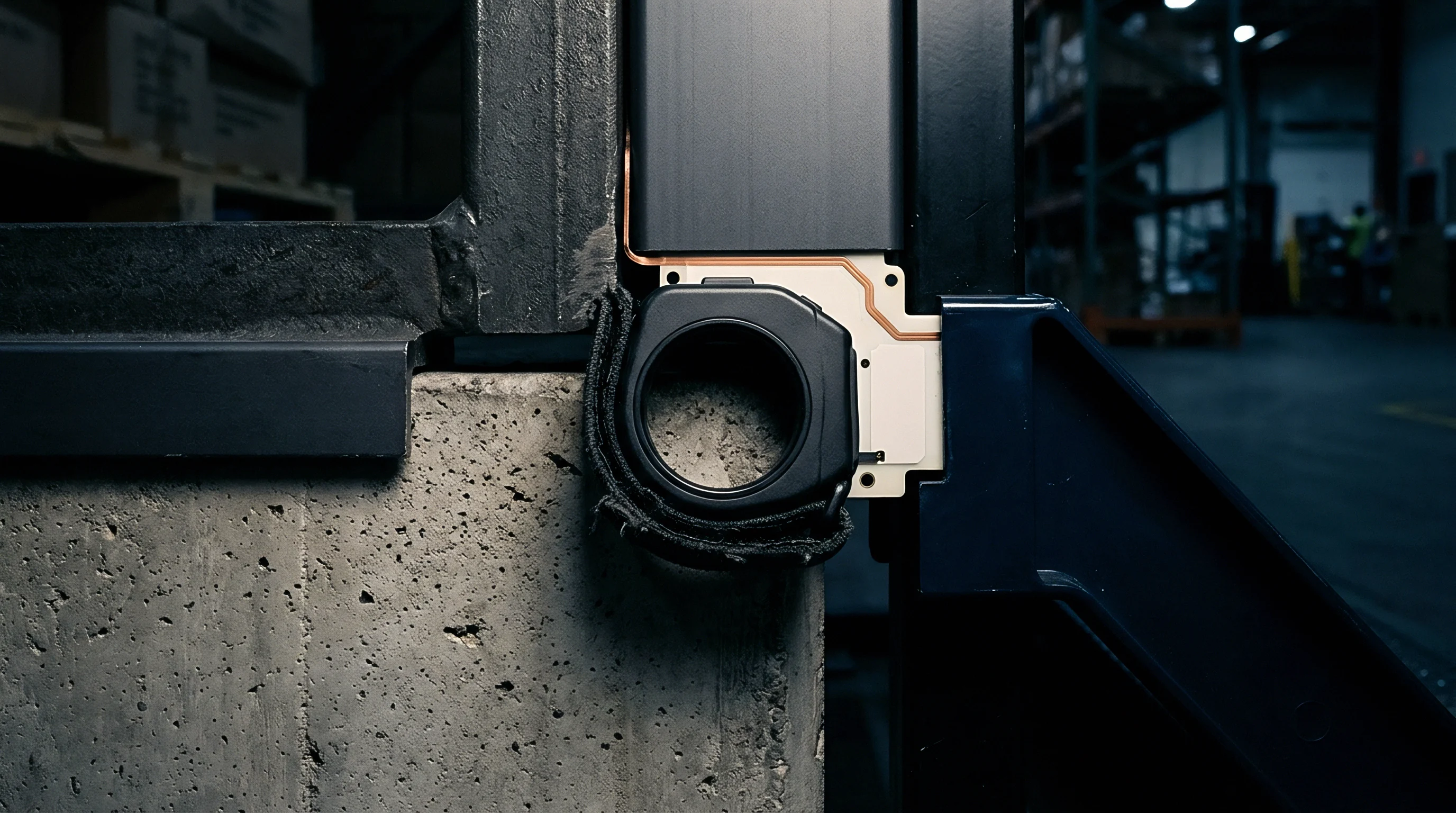

Bushing
Custom sleeve inserts isolate composite structural walls from direct mechanical wear while managing thermal displacement vectors. Bushing geometry varies based on joint load requirements, ranging from plain cylindrical sleeves to complex two-piece flanged hardware assemblies. Flanged inserts transmit clamping force around fastener holes, preventing composite crushing during torque application while allowing internal shoulder pins to slide freely within the bushing inner bore.
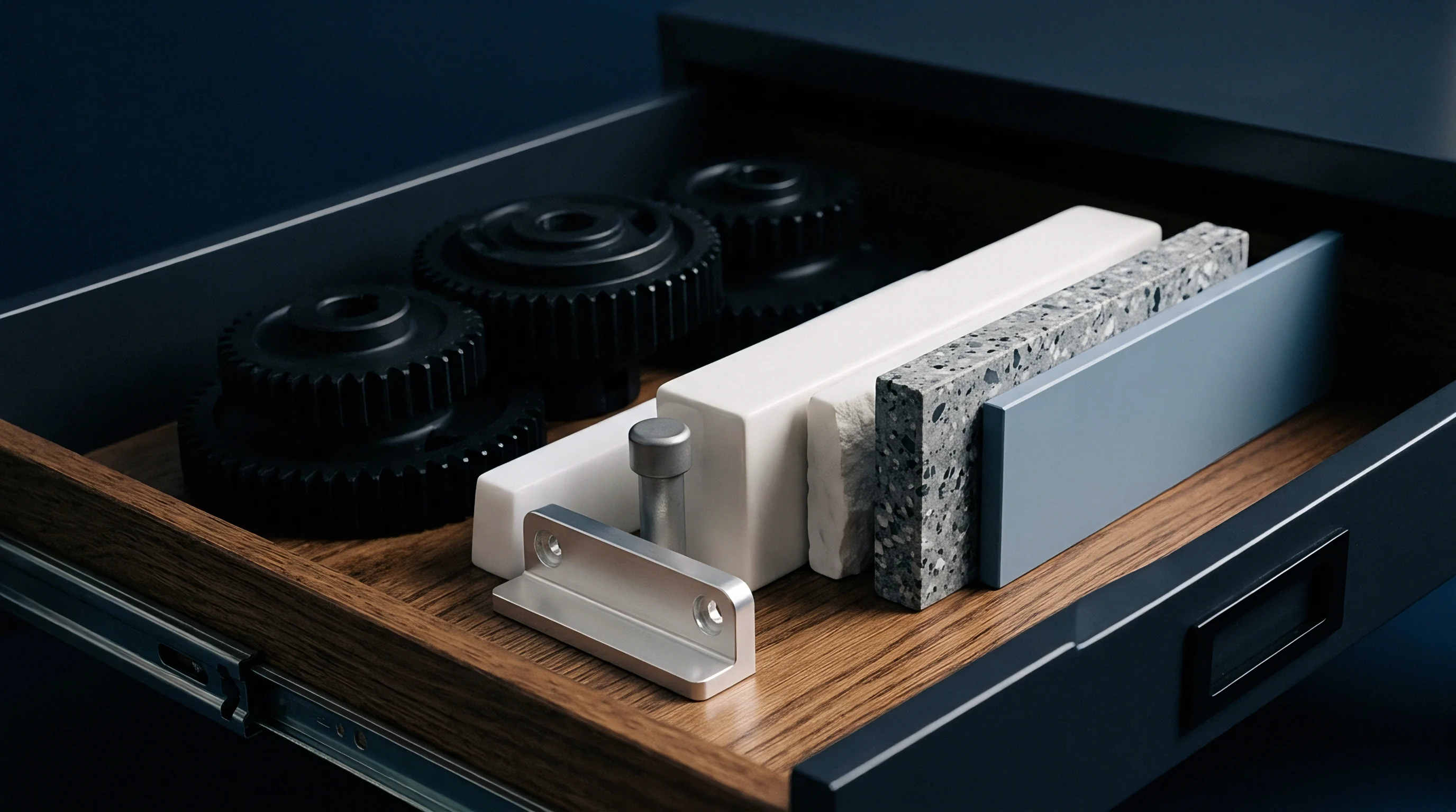
Galvanic Isolation and Material Selection
Direct contact between carbon fiber laminates and active metals initiates severe galvanic degradation in humid, salt-laden marine environments. Carbon acts as a noble cathodic material, driving rapid corrosion of active anodic materials like aluminum or low-alloy steels. Sleeve inserts must utilize galvanic-matched alloys or incorporate non-conductive electrical isolation barriers to prevent structural joint deterioration.
| Bushing Material Matrix | Dynamic Friction Coefficient (vs Ti-6Al-4V) | Maximum Service Temperature (°C) | Galvanic Compatibility with Carbon Fiber | Primary Application Mode |
|---|---|---|---|---|
| Titanium Ti-6Al-4V (Anodized) | 0.22 | 350 | Excellent | Primary shear load sleeves |
| Beryllium Copper (UNS C17200) | 0.18 | 200 | Moderate (Requires barrier) | High-frequency sliding slots |
| PTFE-Lined Bronze Composite | 0.08 | 260 | Good (Insulated backing) | Self-lubricating floating mounts |
| Polyimide (Vespel SP-1) | 0.12 | 300 | Excellent (Non-conductive) | Thermally insulating isolates |
| Nitronic 60 Stainless Steel | 0.15 | 400 | Good | Galling-resistant sliding pins |
Polyimide polymer liners and glass-reinforced epoxy isolation plies break the electrical circuit between carbon fibers and metallic substructures. Placing a single ply of woven structural glass fabric between carbon composite edges and metallic mounting flanges prevents galvanic current flow. Anodized titanium Ti-6Al-4V bushings coated with corrosion-inhibiting primers deliver an optimal strength-to-weight ratio while maintaining complete galvanic neutrality against high-modulus carbon substrates.
Interposing a woven structural glass ply between carbon laminates and aluminum fittings prevents electrochemical joint degradation in marine environments.
Polyimide bushings like Vespel SP-1 deliver high compressive strength coupled with absolute electrical isolation. Non-metallic inserts maintain structural dimensional stability across elevated operational temperatures while eliminating the need for liquid lubricants. Bushing wall thickness selection must balance structural bearing area against hole size expansion penalties; excessively thick bushings require larger hole cutouts that compromise panel net-section tensile strength.
Sleeve vendors frequently state that standard bronze bushings perform adequately in exterior airframe joints without highlighting that uninsulated bronze drives galvanic carbon matrix pitting when exposed to salt-spray environments.
Delamination
Clamp-up torque applied to kinematic fairing fasteners generates through-thickness compressive stresses that can easily crush brittle composite matrices. Carbon fiber reinforced polymers exhibit relatively low out-of-plane compressive strength compared to their in-plane tensile properties. Excessive tightening torque generates interlaminar shear stresses at ply interfaces near the bolt head shoulder, initiating internal matrix cracks that propagate under cyclic aerodynamic loads.

Which Joint Architecture Prevents Thermal Stress Binding?
A floating shoulder screw combined with a controlled-compression Belleville washer stack provides consistent clamp force while absorbing thermal expansions along the bolt axis. Metallic shoulder screws butt directly against internal hardened titanium bushings, limiting washer compression against the composite laminate face. This structural decoupling ensures that the fastener torque establishes proper pin preload without transferring clamping pressure into the composite fairing panel.
Belleville disc springs installed under the bolt head maintain axial clamp force across extreme temperature swings. As temperature changes alter bolt grip length due to differential thermal expansion between the steel bolt and the composite stack, the Belleville washer stack flexes to absorb the dimensional displacement. Maintaining constant clamp tension prevents panel chatter under negative aerodynamic pressure fields while avoiding over-compression at peak thermal soak temperatures.
Torque retention procedures for kinematic fairing mounts rely on mechanical locking mechanisms rather than thread friction alone. Thermal cycling causes standard nylon locknuts to lose prevailing torque over time as the polymer insert experiences thermal relaxation. All-metal prevailing torque nuts, safety wire configurations, or secondary retaining rings ensure long-term fastener security under high-vibration fairing operating conditions.
Procedures for verifying kinematic joint assembly must follow a strict sequential protocol during airframe manufacturing:
- Clean fastener holes and internal slot cavities with isopropyl alcohol to remove machining dust and composite residue.
- Inspect dry-film lubricant coatings on sliding shoulder pins for complete surface coverage and uniform thickness using optical micrometer gauges.
- Insert galvanic isolation sleeves or titanium bushing sleeves into composite panel holes using slow-cure structural epoxy adhesive.
- Position the fairing panel against airframe mounting brackets, aligning the primary fixed location pin prior to installing slotted guide pins.
- Torque central fixed location fasteners to specified assembly limits using calibrated torque wrenches to establish primary structural datum alignment.
- Install shoulder screws and Belleville spring washers into floating slot positions, tightening until the shoulder seats fully against the internal metallic sleeve.
- Measure axial float clearance using feeler gauges to verify that the composite panel retains specified lateral movement limits along thermal expansion axes.
Calibrated Belleville washer stacks absorb axial expansion variances, maintaining continuous joint clamping force across cold-soak and hot-soak flight phases.
According to structural standard NASA-STD-5020A, fastener preloads in composite structures must account for matrix thermal relaxation and moisture swelling, requiring design margins that assume a 20 percent loss of initial clamp force over the operational life of the structure.
Neglecting matrix relaxation leads directly to loose joint hardware, panel vibration, and sudden fatigue failure of the fairing structure.

Allowance
Calculating the total dynamic thermal allowance for exterior fairings requires integrating thermal strain calculations, manufacturing tolerances, and aerodynamic deflection models into a unified dimensional budget. Dynamic tolerance stacks must consider worst-case scenarios where manufacturing hole location errors compound thermal expansion vectors. Neglecting tolerance accumulation leads to premature slot bottoming, converting floating kinematic joints into fixed load transfer points during extreme flight maneuvers.
Thermal Budget and Tolerance Stack Analysis
Consider a representative thermal allowance evaluation for an exterior aircraft composite fairing panel mounted to a 7075-T6 aluminum substructure. The fairing panel measures 1500 mm in total length with attachment slots spaced at 500 mm intervals from the primary central fixed location pin. The assembly operates across an extreme temperature envelope defined from a cold-soak baseline of -55 °C to a maximum ground-soak temperature of +115 °C relative to a standard +20 °C assembly baseline.
The delta temperature for hot-soak conditions equals +95 K. The delta temperature for cold-soak conditions equals -75 K. The relative thermal growth delta per unit length is calculated using the differential expansion coefficient equation:
Differential Expansion Rate = Substructure Expansion Rate – Composite Expansion Rate
Differential Expansion Rate = (23.0 × 10⁻⁶ /K) – (1.2 × 10⁻⁶ /K) = 21.8 × 10⁻⁶ /K
At the outermost attachment slot located 750 mm from the central fixed datum, nominal thermal expansion displacements yield:
Hot-Soak Displacement = 750 mm × (21.8 × 10-6 /K) × 95 K = 1.553 mm outward movement
Cold-Soak Displacement = 750 mm × (21.8 × 10-6 /K) × (-75 K) = -1.226 mm inward movement
Total raw thermal movement range at the outer slot equals 2.779 mm. Manufacturing hole location tolerances contribute ±0.25 mm of positional uncertainty. Fastener shank manufacturing tolerances add ±0.05 mm.
Dynamic airframe flexing under 3g aerodynamic maneuver loads induces an additional 0.40 mm of structural deflection at the fairing interface points.
Summing these individual components establishes the required minimum slot stroke length:
Minimum Slot Length = Nominal Shank Diameter + Hot Movement + Cold Movement + Total Tolerance Stack
Minimum Slot Length = 6.35 mm + 1.553 mm + 1.226 mm + (2 × 0.25 mm) + (2 × 0.05 mm) + 0.40 mm = 10.129 mm
Rounding up to account for safety factors establishes a final machining specification slot length of 10.50 mm. Specifying a slot shorter than 10.13 mm leads to pin contact against the slot end wall during maximum hot-soak conditions, triggering thermal stress lockup across the fairing structure.
A total thermal movement range of 2.78 mm combined with manufacturing tolerances requires a minimum slot length of 10.5 mm for a 1500 mm fairing panel.
Designing composite fairing mounts requires systematic verification across multiple structural criteria:
- Thermal Stroke Margin requires total slot length to exceed combined thermal growth and maximum tolerance stack variations by at least 20 percent.
- Bearing Stress Margin specifies peak operational pin bearing forces to remain under 40 percent of laminate ultimate bearing strength to prevent fatigue degradation.
- Galvanic Isolation Integrity demands electrical resistance between carbon laminate and metallic inserts to measure above 1.0 megohm prior to assembly.
- Acoustic Flutter Resistance mandates lateral slot clearances to stay under 0.05 mm to avoid boundary layer excitation under transonic flight conditions.
- Torque Stability Range ensures Belleville washer compression stays within linear spring rates throughout hot and cold temperature extremes.
Environmental qualification testing validates kinematic joint performance under simulated operational conditions. Qualification protocols subject fully assembled fairing panels to simultaneous thermal cycling and random vibration profiles per RTCA DO-160G Section 5 standards. Feeler gauges and laser displacement sensors track real-time panel growth during environmental chamber testing, confirming that floating pins slide smoothly within guide slots without triggering structural binding or surface galling.
Final acceptance testing requires measuring dynamic joint sliding forces at extreme temperature limits. Surface friction forces exceeding design thresholds indicate alignment errors or insufficient sleeve clearances, requiring immediate joint disassembly and slot dimension verification before approving the fairing structure for flight operation.