High Speed Optical Metrology Refraction Correction in Thermal Wind Tunnels
Ray-tracing correction algorithms for thermal wind tunnels integrate window lensing and fluid density field gradients to bound refraction error under 50 microradians.

Gradient
Thermal gas flows inside high-enthalpy wind tunnels deviate optical rays away from straight trajectories. As gas heats within boundary layers, shock structures, and turbulent mixing regions, local mass density drops sharply. Gas density governs refractive index.
The Gladstone-Dale relation states that the refractive index minus one remains directly proportional to gas density through the media-specific Gladstone-Dale constant. When light traverses a field containing severe spatial temperature variations, local speed of light changes across the wavefront. This phase perturbation steers optical rays toward regions of higher gas density.
High-speed optical metrology systems relying on line-of-sight propagation suffer significant spatial distortion in heated test chambers. Particle Image Velocimetry, Background-Oriented Schlieren, and Laser Doppler Velocimetry register false displacements when photons bend before striking camera image sensors. Photons bend across fluid gradients.
In hypersonic and aerothermal flow testing, thermal boundary layer temperature jumps frequently exceed two thousand Kelvin over distances under three millimeters. The resulting refractive index spatial gradient acts as an uncalibrated optical lens situated directly between the test model and the detector.
Measurement uncertainty escalates rapidly when flow density field dynamics fluctuate at frequencies above ten kilohertz. Uncorrected refraction alters optical path length while steering light beams off their calibrated geometric axes. In tomographic background-oriented schlieren configurations, beam steering deflects lines of sight away from assumed straight projection paths, invalidating standard Radon transform inversions.
Quantitative density field reconstruction collapses unless the computational processing pipeline actively models local ray curvature through the fluid volume.
Deflection angles across a two-millimeter boundary layer at Mach 5 reach up to 14 milliradians when thermal gradients exceed 1200 Kelvin per meter.
Optical Path Distortion in Enthalpy Boundary Layers
Light rays passing through high-temperature gas volumes accumulate spatial phase shifts along their optical trajectories. The total optical path difference equals the line integral of local refractive index along the physical ray pathway. In cold wind tunnels, density variations stem primarily from pressure changes across expansion waves or compression shocks.
Thermal wind tunnels introduce severe enthalpy gradients where gas stagnation temperatures exceed several thousand Kelvin.
Gas density fluctuations induce local refractive index variations that distort optical wavefronts traversing the test section volume. Non-uniform refraction creates dual errors: apparent spatial displacement of seed particles in velocimetry imaging, and loss of image plane focal sharpness due to wave-front phase aberration. High-speed cameras running at frame rates beyond fifty thousand frames per second capture transient aero-optical structures, yet individual frames remain spatially warped by the instantaneous refractive field.
Gladstone Dale Coupling and Variable Gas Densities
The Gladstone-Dale constant depends directly on gas composition and illumination wavelength. Standard dry air exhibits a Gladstone-Dale coefficient near 0.226 cubic centimeters per gram at standard green laser wavelengths. Test facilities deploying alternative working fluids, such as pure carbon dioxide for Martian atmospheric reentry simulation or helium-enriched mixtures for low-density shock tunnels, experience radically different refractive sensitivities.
| Test Gas Composition | Gladstone Dale Constant (cm3/g) | Reference Density (kg/m3) | Refractive Index Sensitivity Range |
|---|---|---|---|
| Standard Dry Air | 0.226 | 1.225 | High sensitivity to boundary layer heating |
| Pure Carbon Dioxide | 0.230 | 1.977 | Severe thermal optical bending at low velocities |
| Pure Nitrogen | 0.238 | 1.165 | Moderate deflection, baseline aerothermal gas |
| Helium Trace Mixture | 0.196 | 0.179 | Low refractive deviation across shock structures |
Quantifying Gladstone-Dale coupling requires simultaneous tracking of local gas composition and temperature fields. In combustion wind tunnels and high-enthalpy arc-jet facilities, chemical dissociation alters species fractions across boundary layers. Dissociated atomic oxygen and nitrogen possess distinct polarizabilities compared to molecular forms.
Neglecting species dissociation across extreme thermal gradients skews calculated density field magnitudes by fifteen percent or more, rendering raw optical displacements useless for aerodynamic force model validation.
Failing to account for gas phase refraction leads directly to corrupted model force predictions, miscalculated heat flux rates, and invalid aerodynamic control stability margins that compromise flight vehicle development.

Glass
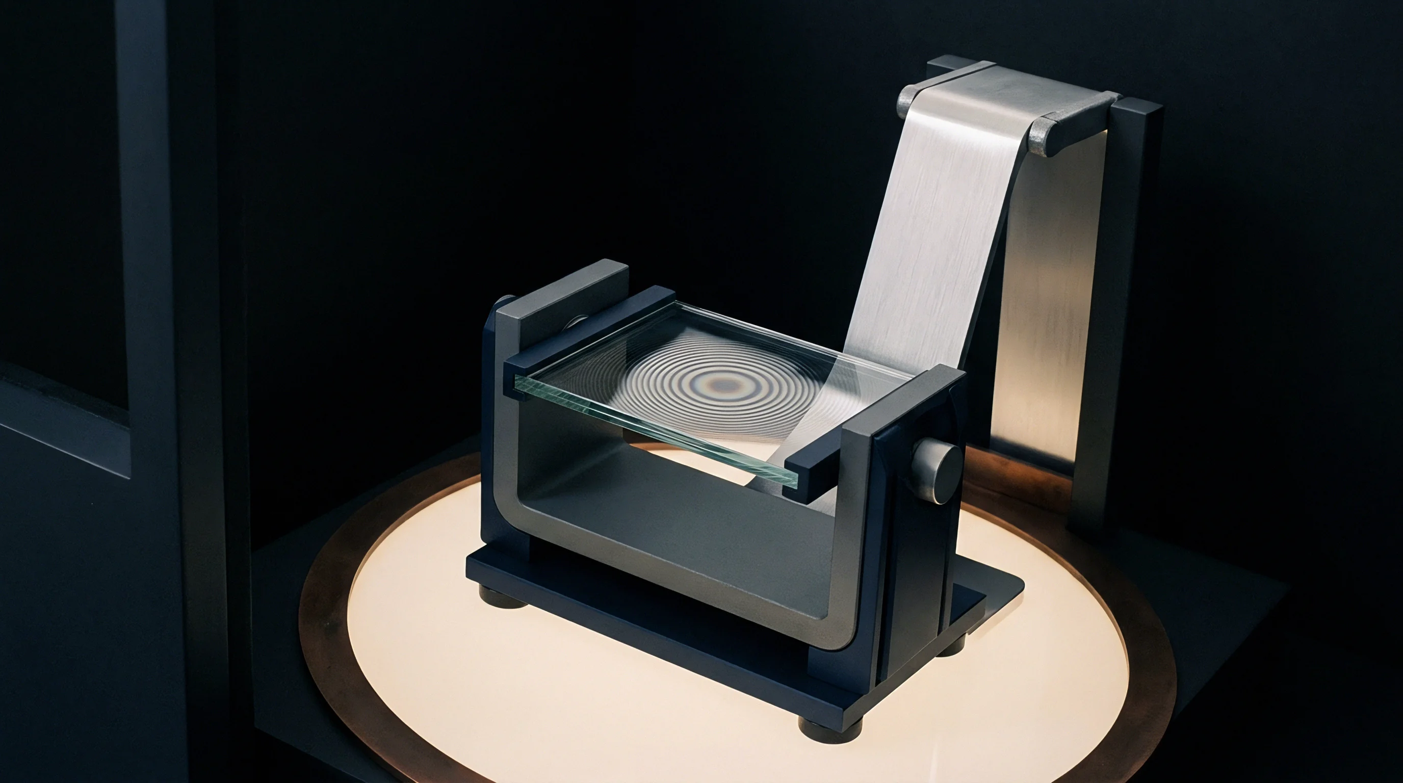
Fused silica and synthetic sapphire test section viewports undergo thermo-mechanical deformation under sustained heat loads. Windows mounted flush with thermal wind tunnel walls experience extreme heat flux on their internal surfaces while external surfaces remain near room temperature. Heat distorts window geometry.
This continuous thermal differential generates a non-linear temperature gradient across the substrate thickness, causing physical window bulging alongside spatial variations in substrate refractive index.
Substrate thermal expansion forces the optical flat outward into the test flow, altering boundary layer trip positions and creating a physical lens shape from a nominally flat optical plate. Simultaneously, thermo-optic coefficient effects shift the internal refractive index of the glass as temperature rises. Fused silica exhibits low expansion.
However, its positive thermo-optic coefficient increases internal index of refraction under heat, introducing severe wave-front retardance independent of the surrounding fluid flow field.
Viewport thermal soaking during long tunnel runs shifts beam focus faster than dynamic software registration algorithms can adjust.

Thermo Optical Distortion Mechanisms in Quartz Viewports
Dual mechanisms drive optical distortion within tunnel windows: surface mechanical displacement and bulk thermal lensing. Surface displacement changes the physical angle of incidence for incoming laser beams, creating geometric beam steering. Bulk thermal lensing alters local optical path length across the window aperture, distorting spatial spatial grid registration targets situated across the test chamber.
Double-pass optical configurations amplify window-induced phase errors. When probe light enters through a thermally stressed window, reflects off a model surface, and exits through a second heated window, window wave-front aberrations combine with gas flow refraction. Disentangling window lensing from fluid density refraction demands continuous window temperature profiling using embedded infrared sensors or thin-film thermocouples.
Material Selection Criteria for High Heat Flux Runs
Selecting viewport substrates involves complex trade-offs between thermal shock resistance, mechanical strength, and optical stability. Standard N-BK7 glass degrades rapidly under high thermal loads due to high thermal expansion and substantial thermo-optic coefficient values. Calcium fluoride offers low dispersion but suffers from poor mechanical strength under pressure differentials.
Synthetic sapphire withstands severe heat flux, yet its natural birefringence complicates polarized optical metrology setups.
Window selection directly limits metrology accuracy in continuous aerothermal facilities. Viewport performance failures manifest across four primary operational mechanisms during prolonged heating:
- Non-uniform thermal lensing occurs when localized boundary layer heating creates uneven refractive index profiles across the optical clear aperture, distorting high-speed imaging targets.
- Substrate mechanical bowing develops as internal pressure and surface heat expansion force planar window surfaces into convex geometries, inducing artificial focal length shifts.
- Index of refraction drift alters absolute optical path length across the substrate as bulk temperatures climb, invalidating ambient sensor baseline calibration setups.
- Acoustic window vibration introduces high-frequency mechanical oscillation into optical paths, blurring high-speed framing camera image exposures taken above twenty kilohertz.
Commercial window vendors frequently claim that custom substrate polished flats eliminate measurement bias, ignoring the physical reality that continuous boundary layer heat flux forces optical substrate lensing regardless of initial surface flatness tolerances.

Ray
Computational optical path reconstruction models calculate the real spatial origin of deflected photons arriving at sensor pixels. Correcting refraction requires replacing straight-line projection assumptions with bent-ray trajectory models governed by the eikonal equation. The eikonal equation models light propagation through non-homogeneous media where local refractive index varies continuously.
Numerical ray tracing discretizes the fluid volume into three-dimensional voxel grids, stepping photons forward along local refractive index gradient vectors.
Forward ray tracing models simulate photon paths from illuminated source grids through window substrates, fluid shear layers, and camera lens apertures onto physical image sensors. Inverse ray tracing solves the opposite problem: converting measured sensor displacement vectors into three-dimensional density field distributions. Iterative ray tracing solvers recalculate light trajectories after every fluid field iteration until simulated image displacements match experimental camera recordings within specified noise tolerances.

Inverse Refraction Algorithms for High Frame Rate Imaging
Processing high-speed camera datasets recorded at fifty thousand frames per second requires computationally optimized inverse ray tracing routines. Direct numerical integration of three-dimensional eikonal equations for every pixel across thousands of time steps demands massive computational clusters. Refraction alters optical length.
Fast algorithms utilize optical transfer matrices or polynomial ray-steering look-up tables pre-calculated across expected ranges of boundary layer thermal gradients.
Iterative wavefront reconstruction converts background-oriented schlieren pixel displacement fields into line-of-sight integrated refractive index distributions. Algorithms initialize with straight rays, calculate local gradient fields, and sequentially update ray curves until spatial displacement Residuals converge below sub-pixel thresholds. Advanced GPU-accelerated solvers process three-dimensional tomographic reconstructions within minutes of tunnel shutdown, enabling rapid test-matrix adjustments during experimental campaigns.
How Does Dynamic Target Distortion Impair Ray Tracing Accuracy?
Target displacement measurements degrade when dynamic thermal gradients cause spatially varying image blur alongside physical displacement. Refraction gradients across shear layers act as micro-lenses with non-uniform focal lengths, stretching dot targets into irregular ellipses. Standard cross-correlation pattern tracking algorithms assume rigid target translation, misinterpreting pattern deformation as pure spatial displacement.
To evaluate computational ray tracing performance under extreme aerothermal conditions, facilities run multi-camera ray tracing validation suites that compare direct wavefront sensor readings against inverse software reconstructions across benchmark heating profiles.
| Correction Algorithm Type | Processing Time Per Frame (ms) | Spatial Position Accuracy (microns) | Density Gradient Error Bound (%) |
|---|---|---|---|
| Linear Straight Ray Approximation | 1.2 | 420 | 22.4 |
| Eikonal Matrix Ray Tracing | 45.0 | 35 | 3.1 |
| Iterative Wavefront Tomography | 180.0 | 12 | 1.2 |
| Polynomial Beam Steering Mapping | 4.8 | 85 | 5.6 |
Ray tracing algorithms depend on strict boundary conditions at window fluid interfaces. Uncorrected spatial shifts in window position alter entry ray angles, injecting systematic bias into the entire downstream flow-field calculation.
- Position the high-density grid target inside the test section under ambient conditions.
- Record reference background images across all sensor channels at maximum laser illumination intensity.
- Fire the enthalpy arc heater while taking continuous spatial displacement fields at 50 kilohertz.
- Compute spatial displacement vectors between distorted run images and unheated baseline frames.
- Solve the eikonal ray equation iteratively to construct three-dimensional refractive index fields.
ISO 21727 verification protocols mandate optical ray steering uncertainty bounds below 50 microradians for high-enthalpy flow velocity field reporting.
Whether dynamic tomographic reconstruction algorithms can resolve turbulent density fluctuations at frequencies above two hundred kilohertz without introducing unphysical computational smoothing remains an open question in modern experimental fluid dynamics.

Target
Physical calibration plates placed inside the test chamber establish baseline pixel coordinates before high-enthalpy run initiation. Optical targets feature high-contrast geometric patterns, such as dot arrays, random speckle fields, or checkerboards, printed on thermally stable substrates. Target alignment establishes camera magnification matrices, lens distortion parameters, and absolute spatial reference frames.
Grid spacing defines spatial resolution.
In background-oriented schlieren metrology, the calibration pattern sits behind the flow section or on the opposite chamber wall. Light emitted or scattered by the pattern traverses the thermal flow field before reaching camera optics. Thermal shifts degrade image contrast.
High heat flux runs cause ambient target plates to expand or warp if exposed directly to tunnel radiation, creating artificial displacement signals that software misinterprets as fluid flow refraction.

Backlit Speckle Array Design and Spatial Resolution
Random speckle patterns optimized for digital image correlation must maintain sub-pixel speckle sizes relative to camera sensor resolution. Speckle size selection balances cross-correlation spatial resolution against optical diffraction limits. Backlit targets utilizing high-output light-emitting diode panels eliminate front-surface reflections and thermal shimmering from hot metal target surfaces.
High-contrast target patterns painted or etched onto ceramic or water-cooled copper plates withstand transient heat exposure inside continuous flow facilities. Backlighting through translucent heat-resistant quartz diffusers yields uniform spatial illumination, maintaining pattern contrast even when glowing boundary layer gas emits intense background light.
Grid Displacement Tracking under High Enthalpy Shock Loads
Shock wave passes create steep, discontinuous optical displacement steps across target image fields. Standard continuous cross-correlation windows fail at shock locations because speckle patterns across the shock boundary undergo severe spatial tearing and brightness shifts. Advanced sub-pixel tracking algorithms utilize adaptive window sizes that shrink near shock fronts to capture localized ray deflections.
Cross-correlation speckle tracking fails when thermal gradient shear layers smudge pattern contrast below fifteen percent.
Validating an optical target setup for high-temperature shock tunnel runs requires executing a systematic pre-test qualification protocol across four key criteria:
- Pattern density verification checks that target speckle dimensions span three to five pixels on sensor arrays to optimize spatial cross-correlation peak fitting.
- Thermal expansion correction factor isolates physical target substrate growth from fluid density refraction by tracking temperature sensors attached directly to target mounting frames.
- Backlight luminance balance confirms target illumination intensity overrides high-enthalpy gas self-emission across all visible imaging wavelengths.
- Cross-camera synchronization check aligns multi-angle stereoscopic sensor exposure triggers within ten nanoseconds to prevent phase lag in tomographic reconstructions.
Federal test facility calibration standards specify that physical reference targets must be certified for spatial flat-grid precision under absolute thermal stabilization before optical deflection data enters official flight certification databases.
Outlay
Capital allocation for aero-optical correction systems balances sensor hardware expenditure against wind tunnel run costs. High-enthalpy wind tunnels consume enormous electrical power, specialized gas mixtures, and single-use model hardware during every test firing. Tunnel run seconds carry high costs.
Arc-jet facilities and shock tunnels incur operational costs ranging from five hundred to five thousand dollars per second of flow duration. Acquiring corrupted optical data during an operational run destroys project budgets through wasted facility time.
Investing in dynamic refraction correction instrumentation, including adaptive optics, high-speed Shack-Hartmann wavefront sensors, and dedicated GPU reconstruction clusters, requires significant upfront capital. However, hardware-driven ray correction prevents test rerun requirements caused by unresolvable aero-optical blurring. Capital commitments demand empirical proof.
Facility managers evaluate metrology capital outlays against lifetime tunnel run efficiency improvements.
Instrumentation Capital Costs against Facility Operational Runtime
Basic optical metrology setups using uncorrected background-oriented schlieren require minimal initial hardware expenditure. However, raw imaging setups yield qualitative density maps that fail to meet quantitative flight system verification standards. Upgrading to real-time wavefront-corrected stereoscopic systems increases upfront instrumentation capital costs by several hundred thousand dollars, while dramatically expanding the usable data yield per tunnel firing.
Adaptive mirrors require fast loops. Incorporating deformable mirrors driven by real-time optical path difference hardware corrects wave-front aberrations directly inside the optical train at kilohertz bandwidths. This hardware intervention reduces post-processing computational overhead, allowing facility engineers to verify flow field baseline conditions immediately between tunnel runs.
| Metrology Architecture Configuration | Initial Hardware Investment ($ USD) | Post-Processing Time Per Run (Hours) | Facility Rerun Risk Reduction (%) |
|---|---|---|---|
| Uncorrected Baseline BOS System | 45,000 | 12.0 | 0.0 |
| Post-Processed Ray Tracing Software Suite | 95,000 | 4.5 | 35.0 |
| High-Speed Wavefront Sensor Array | 280,000 | 0.8 | 70.0 |
| Closed-Loop Adaptive Optics Integration | 650,000 | 0.1 | 92.0 |
Commercial Payback Cycles for Adaptive Optics Upgrades
Payback calculations for high-speed refraction correction systems depend on tunnel occupancy rates and facility operational expenses. In testing environments where wind tunnel time exceeds three thousand dollars per minute, an adaptive metrology system that prevents two failed test campaigns pays for its entire capital acquisition price within a single operational year. Uncorrected optical paths skew velocity.
Accurate velocity and density field measurements accelerate aerodynamic design lock, saving millions in downstream flight vehicle modifications.
Uncertainty bounds dictate data utility. Flight vehicle developers reject metrology datasets carrying unquantified refraction errors, forcing facility operators to absorb re-testing costs under performance warranty guarantees. Implementing verified optical ray tracing pipelines transforms uncalibrated optical imagery into certified quantitative flow fields, securing facility commercial competitiveness.
Optical hardware investments yield maximum payback when metrology integration begins during initial test section design rather than as a retrofit package added after thermal lensing problems emerge.