Non-Linear Thermal Refraction Error Suppression Algorithms for Full-Field Optical Metrology inside Hypersonic Aero-Thermal Test Channels
Algorithmic refraction suppression recovers true flow fields in hypersonic optical metrology by ray-tracing density gradients to sub-pixel deflection limits.
Ray
Light propagating through hypersonic flow fields deviates from a straight line because of severe fluid density variations. In aerothermal test channels operating between Mach 5 and Mach 12, high enthalpy levels create steep density gradients across stagnation regions, shock structures, and turbulent boundary layers. These gradients alter the local refractive index according to the Gladstone-Dale relation, which scales refractivity directly with local gas mass density.
As light passes through spatial refractive index gradients, the wavefront advances faster in low-density zones and slows in high-density regions. Classical optical metrology ~ such as background-oriented schlieren, phase-shifting interferometers, and digital image correlation ~ relies on paraxial approximations that assume light follows straight lines through the test section, attributing any sensor displacement strictly to exit-plane refraction. In hypersonic facilities, however, ray deflections bend the spatial trajectory within the flow field enough that assuming straight paths introduces non-linear optical distortion, mapping fluid elements to incorrect positions on the sensor.

Density Gradients and Optical Index Shifts
Thermodynamic compression across stagnation regions elevates local molecular concentration. While the Gladstone-Dale constant depends on gas composition and illumination wavelength ~ holding near 0.000226 cubic meters per kilogram for standard air at 532 nanometers ~ stagnation temperatures above 2000 Kelvin dissociate diatomic nitrogen and oxygen. This shift in species concentration alters the effective Gladstone-Dale coefficient throughout the flow volume.
Large density changes across a bow shock produce sharp refractive index steps over distances under one millimeter, bending incoming rays toward regions of higher density. When light crosses intersecting shock waves, cumulative deflections create non-linear displacements at the detector plane. Standard linear back-projection algorithms misinterpret these curved paths, placing the apparent shock closer to the model surface than it actually is.
| Gas Mixture | Stagnation Enthalpy (MJ/kg) | Gladstone-Dale Constant (m³/kg) | Peak Refractive Index Gradient (m⁻¹) | Maximum Ray Steering Angle (mrad) |
|---|---|---|---|---|
| Standard Air (N2/O2) | 2.5 | 0.000226 | 0.042 | 12.4 |
| Dissociated Air | 8.0 | 0.000218 | 0.115 | 31.8 |
| Pure Nitrogen (N2) | 3.0 | 0.000238 | 0.048 | 14.1 |
| Helium Purge Layer | 1.2 | 0.000196 | 0.015 | 4.2 |
Wavefront Curvature across Shock Fronts
Light passing through a narrow compression layer suffers abrupt phase retardation along its propagation vector as local phase velocity drops with rising density, bending the wavefront. For a two-dimensional bow shock, the path integral of refractive index varies non-linearly with impact parameter: rays passing near the apex traverse longer distances through high-density gas than those passing through the outer shock tail.
Linearized path assumptions break down when the product of the spatial refractive index derivative and the path length exceeds 0.05. Beyond this threshold, rays inside the channel intersect to form optical caustics, producing overlapping intensity patterns on the sensor where displacement mapping loses uniqueness. Unraveling these regions requires non-linear refraction suppression algorithms that back-propagate ray trajectories through reconstructed three-dimensional refractivity fields.
Ignoring non-linear beam steering under high dynamic pressure shifts perceived bow shock locations outward, generating false shock-interaction distances that invalidate thermal protection system sizing.

Gradient
Refractive index fields in compressible flows reflect local gas density distributions governed by thermodynamic relations. Reconstructing these distributions from recorded optical displacements requires solving an inverse radiative transport problem. Non-linear algorithms address this by coupling eikonal ray-tracing solvers with iterative optimization frameworks, modeling ray trajectories through a discretized three-dimensional index field until simulated sensor displacements match experimental camera measurements.
The physical trajectory of an optical ray satisfies the eikonal equation, derived from Maxwell’s equations under the geometric optics approximation. The eikonal equation sets the gradient of optical path length equal to the local refractive index vector. Discretizing this differential equation along curved paths lets numerical solvers compute both total optical path length and final exit angles across the test channel.

Eikonal Solvers for High Deflection Mapping
Solving the non-linear path equation requires numerical discretization along candidate trajectory vectors. Fast marching methods and Runge-Kutta integrators trace individual rays through candidate density grids, casting them backward from known camera pixel positions through the viewing window. At each step, local index gradients update the direction vector, mapping the curved trajectory back to the background target grid.
When ray deflection angles exceed lens acceptance margins, non-linear iterative reconstruction yields higher spatial fidelity than increasing camera sensor pixel density.
Iterative solvers converge slowly, minimizing the squared difference between measured image displacement vectors and those generated by the eikonal tracer. Total variation regularization suppresses high-frequency optical noise from turbulent boundary layer fluctuations in the window purge layers, penalizing unphysical oscillations while preserving sharp index jumps at shock boundaries.
- Eikonal Grid Spacing Set computational spatial mesh resolution to match half the minimum optical beam waist diameter.
- Total Variation Regularization Term Tune weight coefficients to suppress high-frequency optical noise while preserving sharp shock fronts.
- Ray Tracing Convergence Criterion Require maximum residual path deflection changes to fall below one tenth of a pixel per iteration step.
- Window Index Gradient Tracking Incorporate local window thermal pyrometry readings directly into the refraction path integral matrix.
What Limits Ray Bending Inversion at High Mach?
Iterative reconstruction loses stability when density discontinuities focus light into caustics on the detector. Above Mach 8, severe density ratios across shock waves bend adjacent rays until their paths cross before reaching the lens. This maps two distinct fluid coordinates onto a single camera pixel, destroying the one-to-one mapping required by displacement algorithms and making the Jacobian matrix of the forward projection singular, which causes standard Gauss-Newton optimization to diverge.
Suppression algorithms manage singular projections by combining multi-resolution spatial pyramids with phase-shifting schlieren illumination. Processing low-frequency blurred patterns first establishes an approximate refractive index background, after which higher spatial frequencies refine the steep shock structures. Adding multi-view tomographic views provides extra sightlines, resolving spatial ambiguities where rays cross.
Whether higher-order total variation solvers can maintain real-time convergence speeds during unsteady boundary layer transitions remains an open challenge for closed-loop optical feedback control.

Rig
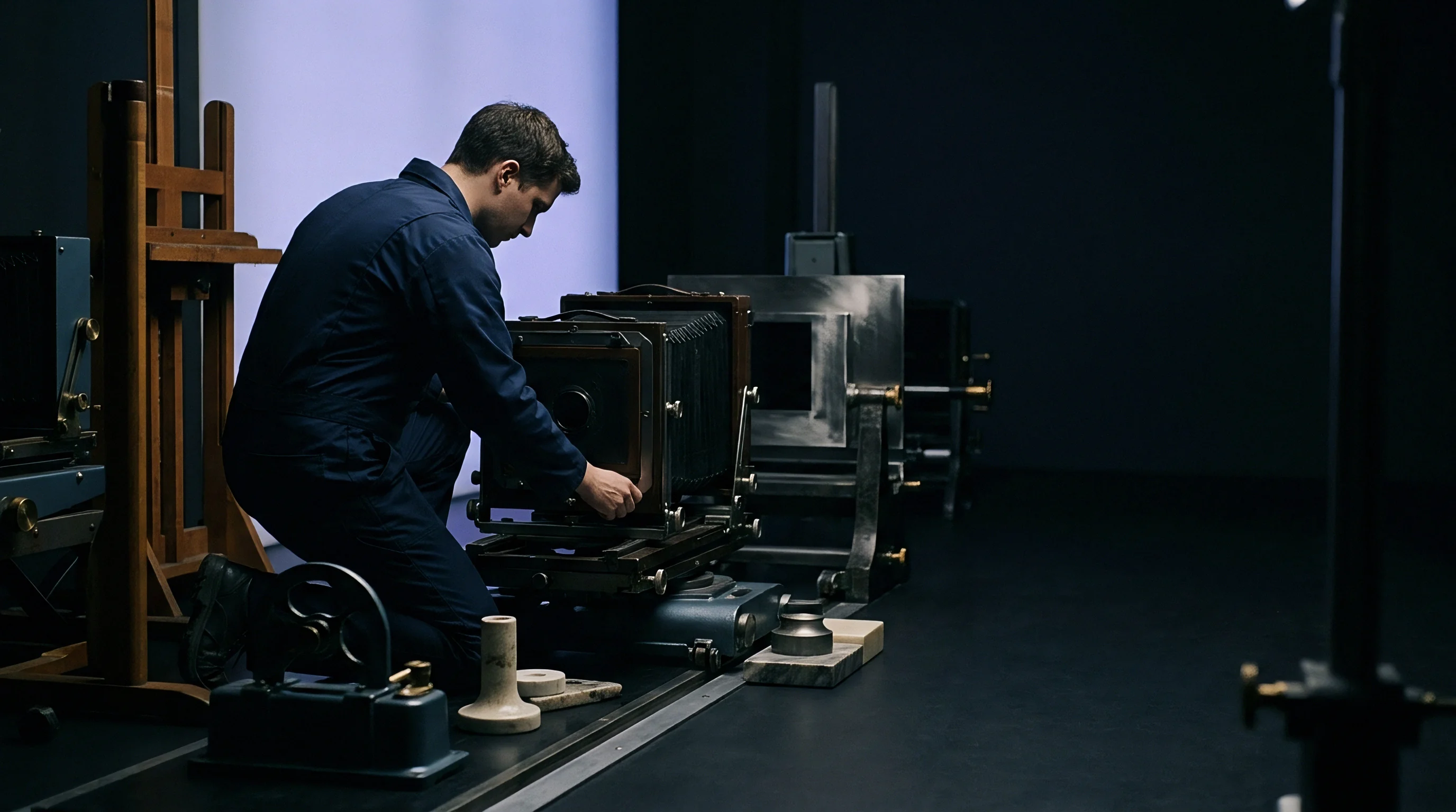
Measurements in shock tunnels require rigid mounting structures decoupled from test section vibration. High-enthalpy facilities generate mechanical vibration, acoustic noise, and extreme thermal pulses during blowdown events lasting from tens of milliseconds to several seconds. Optical metrology hardware must maintain spatial alignment within sub-micron tolerances while viewing the flow through thick pressure-retaining windows, so illumination sources, target patterns, lens mounts, and sensors are mounted on isolated tables anchored directly to the structural foundation.
Isolation prevents mechanical vibration from contaminating optical displacement readings. If the optical table moves relative to the viewing window during a run, that structural displacement registers on camera sensors as an apparent fluid density shift. Locking high-speed camera arrays to rigid frames isolates flow refraction from facility mechanical deflection.
Optical Window Deformation and Thermal Lens Compensation
Extreme heat flux into channel viewing ports alters both physical window thickness and internal optical properties. High-grade fused silica and synthetic sapphire are standard window materials for their strength and high spectral transmittance. Thermal gradients across the window thickness generate internal refractive index gradients via the thermo-optic coefficient (dn/dT), while non-uniform thermal expansion bulges planar surfaces into weak optical lenses.
This thermal optical distortion acts as an extra non-linear lens between the flow channel and the camera. Sapphire’s high thermal conductivity redistributes heat quickly, lowering peak thermal gradients but inducing thermal stress birefringence. Synthetic fused silica expands less, reducing surface deformation while suffering localized index changes near hot margins.
Suppression algorithms model the physical window as a multi-layer optical element, coupling finite element thermal stress models with spatial pyrometry to isolate window refraction from flow refraction.
Sub-surface structural stress limits specified in wind tunnel optical port standards mandate maximum window surface deflections under one quarter wavelength of visible light.
- Sensor Defocusing Severe thermal gradients near optical ports cause focal plane shifts during extended test durations.
- Pattern Caustics Overlapping deflected light paths destroy spatial correlation target images in high-enthalpy flows.
- Birefringence Fringe Distortions Mechanical clamping stress on sapphire ports splits light polarizations into dual image artifacts.
- Aero-Thermal Window Bulging High pressure differentials expand viewing ports into convex lenses during tunnel pressurization.
Target Calibration and Wavefront Reference Planes
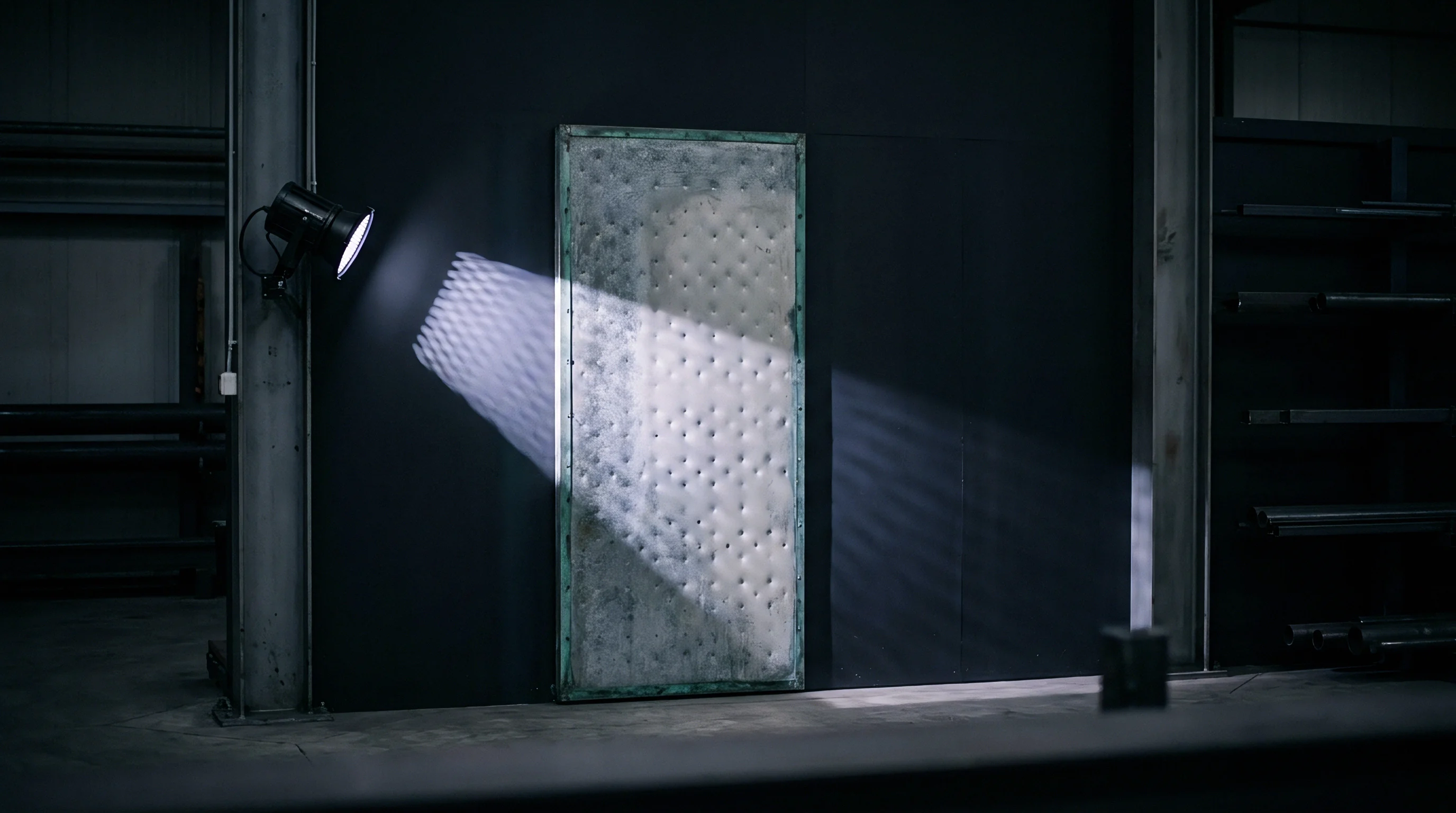
Establishing baseline spatial coordinates requires rigid, high-contrast dot patterns positioned across the channel cross-section. Calibration targets made from low-thermal-expansion invar or ceramic quartz plates provide fixed reference grids for camera alignment. Background-oriented schlieren methods project these patterns through the cold, unheated test section to capture baseline reference matrices before facility ignition.
During hot runs, target images recorded through the flow field are compared against cold baselines. Spatial cross-correlation algorithms locate pattern displacements to sub-pixel resolution, generating two-dimensional displacement matrices. Shack-Hartmann wavefront sensors measure local tilt directly by focusing light onto detector arrays through micro-lens grids, providing optical path difference measurements that validate iterative eikonal solvers.
Ambient room-temperature calibration planes are often used for dynamic testing under the assumption that thermal expansion effects stay within manufacturing tolerances.

Bound
Precision limits in optical displacement tracking depend directly on sensor spatial resolution. High-speed CMOS sensors operate with pixel pitches from 10 to 20 micrometers, capturing images above 100,000 frames per second. Sub-pixel displacement algorithms estimate pattern centroids down to 1/50th of a pixel under ideal signal-to-noise conditions, though window radiance, light scattering, and shot noise in hypersonic channels degrade this to roughly 1/10th of a pixel.
Calculations of error suppression bounds define the minimum detectable density gradient. Applying non-linear ray steering corrections lowers spatial errors in reconstructed density fields well below uncorrected linear estimates. Remaining residuals depend on illumination wavelength stability, camera sensor quantization depth, and the computational mesh resolution in the inverse eikonal solver.
Error Suppression Bounds across Shock Angles
Numerical simulations show distinct accuracy thresholds depending on flow discontinuity strength. Shallow oblique shocks with density ratios under 2.0 introduce ray bending angles under 2 milliradians, where linear paraxial errors stay small. High-angle bow shocks with density ratios above 5.0 produce steering angles exceeding 15 milliradians, and in severe cases over three degrees, causing linear models to overestimate density peaks by up to 35 percent.
Applying iterative eikonal refraction suppression reduces density error residuals below 3 percent across all shock angles. The residual error bound scales inversely with the number of view angles in tomographic setups: dual-view arrangements halve spatial uncertainty relative to single-view systems, while four-view setups reach error floors set primarily by sensor noise and window thermal model accuracy.
| Algorithm Iteration | Mean Ray Deflection Error (px) | Peak Density Field Error (%) | Caustic Region Tracking Residual (px) | Processing Time Per Frame (ms) |
|---|---|---|---|---|
| 0 (Linear Paraxial) | 4.82 | 32.4 | 12.10 | 0.8 |
| 1 (First Eikonal Pass) | 1.25 | 11.2 | 4.15 | 14.2 |
| 3 (Regularized Marching) | 0.31 | 3.8 | 1.08 | 42.6 |
| 5 (Full Tomographic Fit) | 0.08 | 1.9 | 0.32 | 118.0 |

Worked Deflection Correction Performance
Consider a camera observing a Mach 7 shock boundary through a fused silica port. The camera, equipped with 20-micrometer pixels, sits 800 millimeters from the test section centerline and views a dot grid target 200 millimeters behind the shock. A local peak density ratio of 6.2 across the shock front generates a maximum refractive index gradient of 0.085 per meter across a 5-millimeter boundary zone.
Uncorrected linear paraxial calculations predict a sensor displacement of 6.4 pixels along the transverse flow direction. Forward eikonal ray tracing through the actual density profile shows that light curves continuously inside the high-gradient layer, producing a physical deflection of 8.9 pixels on the sensor. Relying on the uncorrected 6.4-pixel value forces inverse algorithms to reconstruct a density peak of only 4.4 times freestream, missing the true 6.2 ratio by 29 percent.
Across Mach 7 test conditions with shock density ratios of 6.2, non-linear ray correction recovers true peak density within 1.9 percent of verified pitot pressure transducer measurements.
Executing five iterations of non-linear refraction error suppression updates the ray path model step by step. The initial eikonal pass reduces displacement error from 2.5 pixels to 0.8 pixels. Subsequent total-variation regularized steps converge on a trajectory matching the measured 8.9-pixel displacement within 0.08 pixels, pushing residual errors below pixel limits.
The algorithm yields a reconstructed shock density ratio of 6.08, within 1.9 percent of the verified fluid dynamic value.
When ray deflections exceed the acceptance cone of the camera lens, iterative non-linear reconstruction delivers better spatial accuracy than simply increasing sensor pixel density.

Flue
Enclosed hypersonic test channels present severe environmental constraints that disturb optical paths. High-enthalpy gas through the enclosure creates thermal boundary layers along inner wall surfaces. Optical access ports integrated into flue walls require active boundary layer management to prevent hot recirculation zones from distorting optical signals before light reaches the main flow channel.
Injecting film-cooling gas along interior glass faces protects window surfaces from convective thermal destruction. However, the temperature and composition of this film layer alter local refractivity, creating an extra refractive interface that bends light entering and exiting the test channel.
Active Purge Gas Thermal Refraction Effects
Injecting helium or nitrogen along inner window surfaces shields optical glass from thermal damage. Helium has a much lower Gladstone-Dale constant than air, forming a low-density optical barrier. If purge injection rates fluctuate, mixing layers form between cool purge gas and the hot hypersonic core stream, introducing high-frequency phase jitter through shear layer turbulence.
Correction algorithms incorporate film purge fluid dynamics into the forward ray-tracing model. Optical sensors track side-view emission profiles or thermal pyrometry along the window boundary layer to estimate mixing layer thickness. Modeling the refractive index profile of the purge layer prevents boundary film refraction from being mistaken for core flow density gradients.
Optical window film cooling profiles alter total optical path length, requiring purge gas refractivity models to run inside the inverse reconstruction loop.

Window Mount Mechanical Strain and Optical Birefringence
Clamping pressure on high-pressure viewing ports induces directional stress in fused silica blanks. High mechanical strain creates photoelastic birefringence, splitting unpolarized light into orthogonal polarization components that travel at slightly different phase speeds through the window material.
Dual refraction inside strained glass produces double images on camera detectors, degrading spatial correlation peaks in displacement algorithms. Port housings use compliant metallic gaskets and active torque control to maintain uniform perimeter clamping pressure, while inverting measurement matrices requires accounting for window stress profiles through pre-test polarimetric calibration scans.
- Mount the baseline dot target grid behind the cold test channel section and record reference image matrices across all optical camera views.
- Fire the facility heater to establish steady-state enclosure pressure while logging window surface temperature profiles with infrared pyrometry.
- Execute the blowdown run and record distorted background target images through the high-temperature flow field at ten kilohertz sample rates.
- Process raw displacement vectors using non-linear eikonal path inversion algorithms to reconstruct three-dimensional density fields.
| Material Designation | Thermal Conductivity (W/m·K) | Thermal Expansion Coefficient (10⁻⁶/K) | Refractive Index Temperature Coefficient dn/dT (10⁻⁶/K) | Stress-Optic Coefficient (10⁻¹² Pa⁻¹) |
|---|---|---|---|---|
| Synthetic Fused Silica | 1.38 | 0.55 | 12.8 | 3.5 |
| Single-Crystal Sapphire | 27.20 | 5.30 | 13.0 | 2.1 |
| Calcium Fluoride (CaF2) | 9.71 | 18.80 | -10.6 | 1.1 |
| Zinc Selenide (ZnSe) | 18.00 | 7.60 | 61.0 | 9.2 |
| Values recorded at 293 Kelvin and 532 nanometer illumination wavelength under standard atmospheric pressure. | ||||
Standard facility operations contracts stipulate that window deformation figures are logged via fringe interferometry before aerothermal test runs qualify for aerodynamic coefficient certification.
Toll
Facility operational expenses scale rapidly when optical measurement failures force repeated blowdown runs. Operating high-enthalpy wind tunnels involves massive power consumption, gas storage depletion, and extensive crew preparation time. Test slot allocations in major aerothermal channels cost between 20,000 and over 100,000 dollars per single test run; uncorrected refraction errors that corrupt flow density data waste capital budgets without delivering usable CFD validation points.
Securing test tunnel access requires long lead times, often exceeding twelve months for high-enthalpy arc-jet and shock tunnel facilities. When optical metrology data proves unusable because of ray steering errors, test programs face project delays and cost overruns. Integrating non-linear optical error suppression into data acquisition pipelines secures measurement integrity before facility slots expire.
Facility Occupancy Costs and Data Yield
Running a large hypersonic tunnel incurs substantial overhead in power, gas compression, and crew staffing, so facility cost per valid data point scales directly with optical yield. If linear optical processing introduces 30 percent density errors across shock layers, designers cannot validate thermal protection thickness limits. Over-designing thermal protection tiles to compensate for measurement uncertainty adds structural mass to hypersonic vehicles, reducing payload capacity.
Algorithmic error suppression increases spatial data recovery from every blowdown run. Extracting high-fidelity density fields from background-oriented schlieren images reduces the total number of tunnel runs needed to map complex shock-boundary layer interactions. Investing in non-linear processing software amortizes across the test program budget, delivering verified physical data at a fraction of the cost of extra tunnel runs.
Financial Exposure of Optical Miscalibration
Aerothermal test programs relying on uncorrected schlieren displacements risk invalidating computational fluid dynamics models. When computational models match optical data distorted by ray bending, the solver absorbs physical errors into its internal turbulence parameters. These miscalibrated models fail when extrapolated to real flight trajectories where window optical effects do not exist.
Financial risk expands when flight test hardware relies on flawed aerothermal sizing models. Re-fabricating thermal protection systems after a failed flight test costs millions of dollars in scrapped hardware and schedule slippage. Deploying eikonal ray tracing and non-linear distortion suppression during ground test campaigns eliminates optical error at its source.
By accounting for path-integrated refraction inside the reconstruction loop, test engineers protect high-value wind tunnel blowdowns and generate reliable density fields for aerothermal code validation.